El mecanismo de atraque común ( CBM ) conecta los elementos habitables en el segmento orbital estadounidense (USOS) de la Estación Espacial Internacional (ISS). El CBM tiene dos lados distintos que, una vez acoplados, forman un vestíbulo cilíndrico entre los módulos. El vestíbulo mide aproximadamente 16 pulgadas (0,4 m) de largo y 6 pies (1,8 m) de ancho. Al menos un extremo del vestíbulo suele estar limitado en diámetro por una penetración de mamparo más pequeña.
Los elementos se maniobran hasta la posición de atraque mediante un sistema de manipulación remota (RMS). Los pestillos y pernos del lado del CBM activo (ACBM) tiran de los accesorios y las tuercas flotantes del lado del CBM pasivo (PCBM) para alinear y unir los dos.
Una vez que se presuriza el vestíbulo, los miembros de la tripulación despejan un paso entre los módulos quitando algunos componentes de CBM. Se instalan conectores de servicios públicos entre los mamparos enfrentados, con un panel de cierre para cubrirlos. El túnel resultante se puede utilizar como muelle de carga , admitiendo grandes cargas útiles de naves espaciales de carga visitantes que no pasarían por un pasillo de personal típico.
Descripción general del diseño
Todos los tipos de CBM cuentan con un anillo de aluminio que se atornilla a la carcasa de presión durante la fabricación del módulo principal. La unión atornillada comprime dos juntas tóricas concéntricas: una es de silicona (para un mejor rendimiento térmico) y la otra es de fluorocarbono (para una mejor resistencia al roce). [2] Un par de anillos acoplados es la estructura principal para cargas de presión críticas para la vida, por lo que los anillos y los sellos se diseñaron según los mismos estándares que las carcasas del módulo. [3] Si los sellos primarios se deterioran, se pueden aumentar con sellos secundarios que se diseñaron y calificaron como parte del CBM. Los sellos secundarios se pueden instalar como una actividad intravehicular (IVA). [4]
La mayor parte del volumen del vestíbulo está reservado para el paso de la tripulación, y normalmente se instala un cierre alrededor del perímetro de la escotilla como límite para el paso. En la mayoría de los lugares, el volumen está reservado para las conexiones de servicios públicos fuera del cierre. El conjunto de servicios públicos es específico para cada par de módulos acoplados. [5]
Principales tipos de CBM
Representaciones de artistas con números de pieza de calificación [6]
Además de sus características estructurales, el ACBM realiza e invierte las funciones básicas asociadas al atraque: [7]
La alineación restringe físicamente el movimiento entre los módulos en cinco de los seis grados de libertad a medida que cambia la distancia entre ellos. [8] Las restricciones son impuestas por conjuntos sucesivos de componentes estructurales. [9]
El operador del RMS recibe una indicación de que los pestillos de captura están listos para operar cuando el módulo entrante se ha colocado correctamente al alcance de los pestillos. La indicación de que los pestillos están listos para operar se proporciona mediante cuatro mecanismos: uno en cada cuadrante, asociado con cada pestillo.
El módulo entrante es capturado por cuatro pestillos, que lo atraen mediante una combinación de rotación y traslación para alinear el PCBM con el ACBM con un pequeño espacio residual. [10]
Se establece una conexión estructural rígida. Cada uno de los 16 pernos accionados por motor en el ACBM cruza el espacio residual para enroscarse en una tuerca en el PCBM. Los pernos se aprietan en un proceso de varias etapas que gradualmente conforma las dos bridas, comprime los sellos CBM/CBM y precarga la unión CBM/CBM.
Se especificaron dos tipos funcionales para el ACBM. [11] El ACBM Tipo I, con un complemento de 24 mecanismos independientes, puede encontrarse orientado axial o radialmente en el módulo original. Puede estar orientado a cualquiera de las seis orientaciones orbitales, [12] por lo que puede estar en cualquier lugar dentro de un amplio rango de temperaturas al inicio de las operaciones de atraque. [13]
El ACBM Tipo II amplía el diseño del Tipo I con componentes para proteger su módulo original cuando no hay nada atracado en un puerto. Cuatro de los componentes son mecanismos que se pueden desplegar para salir del camino del módulo entrante. La tripulación retira otros después de que se presuriza el vestíbulo. El Tipo II se utiliza donde los puertos de otro modo quedarían expuestos durante largos períodos de tiempo, o en direcciones que experimentan condiciones agresivas previas al atraque. [14] El ACBM Tipo II se encuentra en los puertos radiales de los nodos de recursos y puede orientarse en cualquier orientación orbital.
PMA 1 y PMA 2 fueron lanzados en los ACBM axiales del Nodo 1.
El PCBM incorpora accesorios y estructuras de alineación correspondientes a los del ACBM Tipo I. 32 de los accesorios son en sí mismos mecanismos accionados por resorte, activados durante la captura y la rigidización por los componentes correspondientes del ACBM. [15] El sello primario CBM/CBM también es parte del PCBM, al igual que los resortes de separación/empuje precargados para estabilizar su movimiento relativo cuando la unión CBM/CBM está casi acoplada. [16]
Se especificaron dos tipos para el PCBM, que se diferenciaban únicamente en la durabilidad de su sello. El material de silicio S383 del sello del PCBM Tipo I es más tolerante a la diferencia de temperatura previa al atraque entre los dos módulos que el fluorocarbono V835 del Tipo II. El S383 también es más resistente al oxígeno atómico encontrado en órbita antes del atraque. [17] El Tipo II se utilizó para lanzar elementos pequeños en la bahía de carga útil del transbordador mientras estaba atornillado a un ACBM o a un equipo de soporte de vuelo similar porque el material V835 es más resistente a los efectos dañinos del frotamiento bajo vibración. [18]
El PCBM siempre se ubica en un extremo del módulo principal. Puede estar unido a un mamparo o como un anillo final en una sección de barril de la estructura primaria que está abierta al vacío antes del atraque. [19] Los PCBM se unen a módulos que tienen una amplia gama de masas térmicas, por lo que también pueden experimentar una amplia gama de condiciones de temperatura inicial. Por la naturaleza de la operación, el PCBM siempre está orientado en la orientación de vuelo opuesta a la del ACBM, por lo que las diferencias de temperatura pueden ser significativas. [20]
Operaciones
Consulte la Galería de operaciones para ver más gráficos. Consulte la Tabla de misiones para ver los eventos de atraque individuales.
Post lanzamiento
STS-130 MS Robert Behnken se toma un descanso durante la preparación de la EVA del ACBM Nadir del Nodo 3. [6]
Los ACBM requieren una EVA para prepararse para su primer uso en órbita. Los ACBM de tipo I, que se encuentran normalmente en los puertos axiales, suelen tener una cubierta tipo "gorro de ducha" que dos miembros de la tripulación de EVA tardan unos 45 minutos en quitar y guardar. Los ACBM de tipo II, que se encuentran en los puertos radiales de nodo, requieren la liberación de las restricciones de lanzamiento para las cubiertas M/D desplegables. La liberación de las cubiertas accionadas por resorte requiere la activación de los pestillos de captura para cerrarlas de nuevo después y, por lo tanto, activa los indicadores de listo para cerrar. Incluyendo la inspección, cada puerto radial tiene un presupuesto de unos 15 minutos para un solo miembro de la tripulación de EVA, asistido por la tripulación de IVA para operar el ACBM según sea necesario. [21] [22]
Los elementos de tamaño real lanzados en el NSTS tenían cubiertas protectoras sobre el sello del PCBM. Dos miembros de la tripulación de EVA necesitaron entre 40 y 50 minutos cada uno para quitar y guardar las cubiertas del PCBM, inspeccionar el sello mientras lo hacían y limpiarlo si era necesario. [23] Los PCBM de tipo II utilizados como interfaz de lanzamiento se inspeccionaron después de desatornillarlos, ya que no se instalaron cubiertas. Para los vuelos logísticos, la inspección se realiza solo con cámara. [24] [22]
Atraque
Preparación
Comprobación de un mecanismo de atraque común activo durante la Expedición 56 (aproximadamente 10 veces la velocidad real). [6]
El PCBM no requiere preparación para el atraque más allá de lo que se requiere después del lanzamiento. La preparación del ACBM para el atraque lleva aproximadamente una hora, comenzando con la selección de los servicios de apoyo (energía, datos) y la activación secuencial de cada conjunto de panel de control (CPA). Se seleccionan dos CPA como controladores maestros primario y secundario.
La activación ejecuta la prueba incorporada e inicializa los contadores de posición de los actuadores. Cada actuador de perno se extiende dos revoluciones y luego se retrae tres para verificar la operatividad tanto del perno como del motor. Los pestillos se accionan uno a la vez hasta la posición abierta que, para los puertos radiales de nodo, despliega las cubiertas M/D. Los 20 actuadores se configuran en las posiciones iniciales operativas (0 revoluciones para los pernos, 202° para los pestillos). Se realiza una inspección remota para verificar que los pestillos estén completamente desplegados y que el corredor de acoplamiento y la superficie estén libres de obstrucciones. [25]
Las contingencias consideradas durante la preparación incluyen la limpieza de la cara del anillo del ACBM y las acciones correctivas de EVA que involucran las cubiertas M/D, así como el CPA, el enganche de captura y los indicadores de listo para enganchar. Existen procedimientos de resolución específicos para la pérdida de energía y soporte de comunicaciones al CBM. [26]
Maniobra
El módulo equipado con PCBM se introduce en la zona de captura mediante un sistema de manipulación remota (RMS) operado por telerrobótica. Se han utilizado dos RMS diferentes para atracar los módulos: el RMS del transbordador de 6 articulaciones (SRMS, o " Canadarm ") y el RMS de la estación espacial de 7 articulaciones (SSRMS, " Canadarm 2 ").
La operación de maniobra comienza con la adquisición de la carga útil por parte del efector final del RMS. Este paso se conoce como "captura" o "agarre". Durante la era del NSTS, las cargas útiles solían llegar a la bahía de carga útil del transbordador. Durante el agarre, las articulaciones del SRMS se "cojeaban", lo que le permitía adaptar su postura a la ubicación exacta de la carga útil. El SSRMS normalmente agarra una carga útil que vuela libremente y que se ha maniobrado para mantener una distancia y orientación constantes con respecto a la ISS. Una vez agarrado, el RMS mueve el módulo cambiando los ángulos de sus articulaciones. El movimiento del módulo a menudo debe estar coreografiado con otras partes móviles de la ISS, como los paneles solares.
Animación de la NASA de tres operaciones de atraque con el transbordador RMS en la misión STS-98. [6]
Al menos dos sistemas dedicados han proporcionado al operador del RMS información visual sobre el movimiento del PCBM. Los primeros atracaderos se guiaban utilizando una técnica de retroalimentación fotogramétrica denominada Sistema de Visión Espacial (SVS), que rápidamente se determinó que no era adecuada para el uso general. El SVS fue reemplazado por un Sistema de Cámara de Atraque en la Línea Central (CBCS) dedicado a tareas específicas, utilizado por primera vez en la misión STS-98. [27]
El tiempo necesario para completar la maniobra RMS depende completamente de la trayectoria que se debe seguir y de las restricciones operativas que se deben tener en cuenta. Lo mismo se aplica a todos los planes de contingencia. Cerca del final de la maniobra, el operador negocia un corredor estrecho mientras el PCBM comienza a acoplarse con el ACBM. La operación termina cuando el operador del RMS ve cuatro indicaciones de listo para engancharse en el ACBM objetivo o concluye que solo se pueden lograr tres. Debido a que el RTL es un mecanismo accionado por resorte, el RMS termina con energía almacenada y queda en un estado que puede resistir la fuerza de separación. [28]
Compañero
Las dos mitades del CBM se unen nominalmente en tres operaciones:
Capture adquiere y alinea el PCBM entrante con respecto a la geometría del ACBM.
Nut Acquisition enrosca cada perno motorizado en su respectiva tuerca
Boltup precarga completamente la unión entre las dos mitades
Se han ejecutado al menos dos protocolos de captura distintos en órbita. Ambos protocolos emiten un comando de captura de "primera etapa" en un ángulo de eje indicado entre 185° y 187°. La captura de primera etapa garantiza que cada pestillo esté colocado por encima de su respectivo ajuste, lo que se verifica operativamente evaluando su estado de conmutación. El RMS sigue controlando la posición y orientación del elemento, y las cargas ejercidas por los pestillos de captura siguen siendo bajas. La captura de primera etapa, que tarda unos 15 segundos en completarse, está restringida a las regiones orbitales donde los controladores de tierra pueden supervisar el progreso casi en tiempo real. Para controlar las cargas espurias cuando el elemento de atraque es grande, el sistema de control de actitud de la estación puede mantenerse en deriva libre y se prohíbe el ejercicio de la tripulación. [29]
Los dos protocolos difieren en la forma en que los pestillos atraen las dos mitades hasta el alcance de los pernos motorizados. Durante la era NSTS, se emitía un solo comando de "captura" de segunda etapa después de que el SRMS se colocara en "modo de prueba". Se ejecutan cinco etapas de captura cuando se utiliza el SSRMS para limitar la posibilidad de que se acumulen cargas en los brazos de sus brazos si se producen eventos de frenado fuera de lo nominal. En cualquier caso, la captura impulsa los pestillos hasta el ángulo de eje indicado de 12° en un tiempo de actuación de aproximadamente 108 segundos. En ambos protocolos, la energía residual en los RTL puede hacer que se abran brevemente porque los pestillos no están "enganchados" a sus accesorios hasta mucho por debajo de la posición inicial de 187°. [30]
Las operaciones RMS y CBM están resaltadas en amarillo y azul, respectivamente, en esta cronología de atraque del paquete de ejecución STS-120/FD04 (NASA/MCC, 2007). Las restricciones están resaltadas en rojo. Los controladores de tierra emitieron comandos de Bolt propulsado después de la captura de la segunda etapa. [6]
Una vez que el operador concluye que el proceso de captura se ha completado con éxito, los 16 pernos accionados se activan a 5 rpm con un límite de precarga de 1500 lbf (6700 N). A medida que los separadores térmicos comienzan a entrar en contacto con sus respectivas placas de impacto, la carga resultante es informada por la celda de carga de cada perno. Esta fase "ABOLT" termina individualmente para cada perno en función del par, las revoluciones o la carga indicada. Los pernos que terminan antes pueden ver su carga indicada cambiar a medida que los pernos posteriores asientan sus tuercas. Los operadores, que pueden estar en tierra, evalúan la condición resultante para determinar si la condición de carga es aceptable. Si es así, se levantan las restricciones en el control de actitud y el ejercicio. El RMS libera (desagarra) la carga útil y puede proceder a otras tareas. [31] [32]
Si el análisis térmico previo a la misión indica que la diferencia de temperatura entre las dos mitades del CBM es excesiva, se mantiene la condición ABOLT durante un período prolongado. La "retención térmica" permite que los dos lados se acerquen a una temperatura común. Luego, los pernos accionados se aprietan en seis pasos hasta su precarga completa. Cada comando se emite a cuatro pernos a la vez, espaciados a intervalos de 90°. Algunos pasos pueden, a discreción del operador, ejecutarse más de una vez. La activación final del perno está prevista para 60 minutos, pero puede variar bastante según la cantidad de iteraciones de precarga incremental que se ejecuten. [33]
Una vez que el operador determina que el proceso de cierre se ha completado con éxito, se ordena a los pestillos que pasen a la posición "cerrados" y se desactivan los CPA. Los recursos de energía, comando ejecutivo y datos están disponibles para reasignarlos a otras tareas.
El diseño del CBM permite adaptarse a varias situaciones fuera de lo normal. El sello CBM/CBM puede adaptarse a cualquier falla de un perno durante la operación de acoplamiento, permitiendo que el vestíbulo mantenga la presión atmosférica. Cualquier falla de dos pernos puede tolerar cargas mecánicas, siempre que no estén uno al lado del otro y el vestíbulo no esté presurizado. La pérdida de un solo pestillo y de un solo indicador de listo para enganchar puede tolerarse sin poner en peligro el éxito de la misión, y los propios pestillos están diseñados para adaptarse a la posibilidad de modos de falla de "frenos activados" en el SRMS. Se dispone de una lógica de resolución detallada para la pérdida de energía y comunicación, así como de secuencias de resolución para pestillos que "pierden" sus ajustes o se atascan en una carrera parcial. Los procedimientos de contingencia en esta fase de las operaciones también abordan el frenado anormal del SSRMS y la "protección rápida" si otros sistemas en la ISS o el transbordador requirieran una salida inmediata. [34]
Operaciones de IVA
La piloto del STS-92, Pamela Melroy, identifica dos conjuntos de paneles de control (CPA) que deben retirarse del vestíbulo Zenith del Nodo 1. [6]
El equipamiento del vestíbulo incluye la instalación del equipo, la comprobación de fugas y la reconfiguración mecánica. El tiempo y el esfuerzo necesarios dependen de la configuración del ACBM, la cantidad y el tipo de componentes del CBM que se deben quitar y las interfaces que se deben conectar entre los dos elementos. Se puede presupuestar hasta diez horas, aunque, al menos en algunos casos, ese tiempo se puede pausar para realizar una "comprobación de fugas finas" más extensa mediante la caída de presión antes de abrir la escotilla hacia el vestíbulo.
Debido a que se superponen al corredor de la tripulación a través del vestíbulo, los CPA siempre deben estar despejados, [35] y siempre es necesario quitar cualquier cubierta a lo largo de la escotilla en el elemento recién atracado. Cuando los elementos permanecerán acoplados durante largos períodos de tiempo, otros componentes de CBM pueden quitarse para un almacenamiento seguro o reutilización. Los puertos radiales del nodo requieren de 20 a 40 minutos adicionales para la remoción y almacenamiento de la sección central de la cubierta M/D. Un panel de cierre se instala típicamente alrededor del perímetro interior de las dos vigas de escotilla enfrentadas, para mitigar la acumulación gradual de escombros alrededor del perímetro del vestíbulo. [36]
Se prepararon con antelación operaciones de contingencia detalladas, que abordaban tanto las reparaciones como el mantenimiento preventivo, para los componentes accesibles desde el interior. Los procedimientos generalizados para localizar fugas atmosféricas en el vestíbulo existen desde al menos la etapa de ensamblaje 4A de la ISS, al igual que los procedimientos de instalación de contingencia para los tres conjuntos de sellos IVA. Los informes de daños a los conectores CPA (tanto en tierra como en órbita) llevaron a la implementación de procedimientos de mitigación de riesgos en la STS-126 . [37]
Desembarque
La remoción de un elemento esencialmente invierte el proceso de atraque. [38] Varía según los detalles de cómo se configuró el vestíbulo para las operaciones. La implementación más común comienza con el desequipamiento del vestíbulo cuando se reconfigura para desatracar un elemento logístico desde el puerto radial del nodo. El procedimiento se presupuestó originalmente para dos miembros de la tripulación y una duración de 4 horas. Retira los elementos que cruzan el plan de interfaz ACBM/PCBM (cierres, puentes de servicios públicos y correas de conexión a tierra), instala el hardware CBM esencial para las operaciones de desatraque (por ejemplo, CPA, cubiertas térmicas) y cierra la escotilla. [39]
Posteriormente, se instalan en el interior de la escotilla equipos de prueba de caída de presión, incluidos sensores y electrónica de apoyo, y un puente de acceso de vacío de 35 pies (11 m) de longitud. Una vez instalados, el vestíbulo está listo para un período de despresurización de aproximadamente 40 minutos, incluidos períodos de espera para la verificación de fugas. El objetivo de presión crítica (absoluta) es de 2 mmHg (267 Pa) para evitar daños a los sellos CBM durante la despresurización. [40]
Al igual que en la preparación previa al atraque, se configuran los servicios de apoyo para suministrar energía y datos al CBM. Se aplica energía, se seleccionan dos CPA para su uso como controladores maestros primario y secundario, y se inicializan los controladores de motor individuales. Se emite un comando "DBBoltck" a los pernos motorizados y se ordena individualmente a los pestillos de captura que se ubiquen en un ángulo de eje de 212°. Luego, los pestillos se colocan en su posición nominal de "captura completa" de 12°. El CBM se deja en una condición de "espera" o se apaga. [41]
Cierre posterior al atraque de las cubiertas en el nadir CBM de Harmony.
La liberación del elemento PCBM de la condición de acoplamiento duro lleva alrededor de 90 minutos. Comienza con el aflojamiento de los 16 pernos accionados aproximadamente 0,4 revoluciones, lo que lleva menos de cinco minutos. [42] Se requiere que los 16 pernos tengan una carga residual positiva después de que se complete el paso. [43] Luego se extraen por completo conjuntos de cuatro pernos, cada conjunto demora aproximadamente 6:30 para alcanzar una posición nominal de 21,6 revoluciones. Se requiere que la pinza RMS y el control de actitud de deriva libre estén en su lugar antes de retirar el tercer conjunto. Después de que se hayan extraído los 16 pernos, se despliegan los pestillos de captura, lo que permite que los indicadores de listo para enganchar comprimidos empujen contra las guías de alineación del PCBM. El elemento que se aleja es maniobrado por el RMS y, en los puertos radiales del nodo, se cierran las cubiertas M/D desplegables. Luego, el ACBM se apaga quitando la energía de los CPA. [44]
Las soluciones para contingencias durante el desatraque son generalmente similares a las de preparación y ejecución de operaciones de apareamiento. Muchas de ellas terminan efectivamente con instrucciones para un reatraque de contingencia para permitir la remoción y reemplazo de componentes del CBM. El esfuerzo para reacondicionar el vestíbulo para el desatraque del CBM lo hace generalmente inadecuado para salidas de emergencia. [45]
Oportunidades
El diseño original de la ISS requería que se instalara un elemento Hábitat en el puerto del Nodo 1 (Unity) orientado hacia el nadir, y las penetraciones del mamparo se diseñaron en consecuencia. A medida que la estación maduraba a través de las primeras fases de ensamblaje, se planeó que el Nodo 3 se ubicara en esa ubicación. Más tarde se hizo evidente que la instalación en el mamparo del lado de babor conferiría importantes ventajas operativas. Desafortunadamente, la ruta original de los servicios públicos dentro del Nodo 1 requirió una importante modificación en órbita para permitir el cambio. El gran diámetro del CBM permitió el uso de PMA3 como cierre de contención de presión durante el esfuerzo, de modo que los pasamuros se pudieran quitar y reemplazar sin EVA. El PMA3 fue trasladado durante la Expedición 21 al CBM del lado de babor, y "... el cableado de agua potable, ISL y datos 1553 y la instalación de conductos, cables y mangueras de IMV [ventilación intermodular]..." se conectaron en preparación para la llegada del Nodo 3. El mamparo reconfigurado se probó para detectar fugas antes de trasladar el PMA3 de regreso a su ubicación de almacenamiento, y el Nodo 3 se instaló en la ubicación recién preparada en la STS-130 . [46]
La profundidad, el diámetro y la accesibilidad del CBM también se han aprovechado para facilitar la distribución de CubeSats desde el sistema de despliegue SlingShot. El armazón se monta en la envoltura interior del PCBM en vehículos logísticos (por ejemplo, Cygnus ). El módulo de esclusa de aire NanoRacks de Bishop (NRAL) aprovecha la sólida interfaz entre el ACBM y el PCBM para atracar y desatracar repetidamente una "campana" que alberga una capacidad similar. [47]
Historia del desarrollo
Los principales factores que influyen en el CBM se mostraron durante el vuelo posterior al desacoplamiento de la STS-135 . La trayectoria del PCBM durante la captura es inducida por el RMS (1). El RMS interactúa con módulos que varían en peso desde la Cúpula (2) y los PMA (3) hasta Kibō (4). La masa interactúa con la iluminación para generar diferencias de temperatura entre los anillos del CBM. Esto se suma a las deflexiones inducidas por la presión, especialmente para los puertos radiales (5). [48]
El concepto de atraque del programa espacial estadounidense se desarrolló para mitigar los problemas de mecánica orbital que surgieron durante la evolución del acoplamiento. Aunque no fue el primer mecanismo desarrollado específicamente para el atraque, el CBM fue el primer dispositivo de este tipo diseñado en los EE. UU. específicamente para ensamblar juntas estructurales que soportarían la presión del nivel del mar. Integra cuatro características arquetípicas:
Las estructuras presurizadas experimentan presión interna además de sus otras cargas primarias. [49] Se las considera críticas para la vida cuando se las utiliza como casco presurizado de un compartimento tripulado. En ese contexto, reciben especial atención por cuestiones como cargas, tasa de fugas, redundancia de sellos y prácticas de verificación. También se examinan minuciosamente los efectos de su falla. [50]
Las bridas externas están sujetas tanto a cargas mecánicas como a cargas inducidas por la presión en sus recipientes a presión originales. La rigidez relativa de la brida determina cómo cambiará de forma el extremo libre. Se deben tener en cuenta las distorsiones cuando se fija algo a la brida. [49]
Los conjuntos mecánicos móviles transmiten fuerzas de forma diferente a medida que cambia su postura. Sus cargas se ven influenciadas por la fricción interna y, a menudo, requieren más iteraciones de análisis y diseño que las estructuras. En el caso de CBM, la trayectoria de carga incluye tanto el módulo como el RMS, por lo que puede ser muy complicada. [51]
Las juntas estructurales que resisten el alto vacío están diseñadas para limitar estrictamente los espacios a lo largo de la junta, y las condiciones en las que se ensamblan se gestionan con cuidado. En el caso del CBM, estos problemas se agravan durante el montaje por el lavado de los sellos a medida que se conforman las deflexiones previas al atraque, y por el polvo y los residuos atrapados en la junta. [52]
El uso de estas características en una nave espacial implica consideraciones especiales debido al entorno agresivo. A la altitud típica de la Estación Espacial Internacional (ISS), de 255 millas náuticas (472 km), la NASA identifica siete factores para ese entorno: [53]
La intensidad del flujo de meteoroides que inciden en el CBM varía considerablemente según la orientación de la instalación. [6]
La composición, las propiedades y las condiciones de la atmósfera neutra ambiental. En particular, el oxígeno atómico (OA) es altamente corrosivo para muchos materiales. Los elastómeros, como el sello frontal del PCBM, son particularmente sensibles al OA. La baja presión y la baja humedad absoluta también afectan el coeficiente de fricción para muchas combinaciones de materiales. La exposición a presiones muy bajas también cambia la composición química de ciertos materiales con el tiempo. [54]
Fuentes y sumideros de energía radiante fuertemente direccionales . El montaje, las propiedades ópticas y el aislamiento de los componentes expuestos de la nave espacial están diseñados para mantener temperaturas aceptables. En algunos casos, la orientación orbital de una nave espacial entera se controla dinámicamente para mitigar estos efectos. [55] [56]
El campo geomagnético puede interferir con componentes eléctricos sensibles (como los sensores, interruptores y controladores del ACBM). Los efectos pueden incluir una falla total cuando los componentes pasan a través del campo. [57]
Gases ionizados que contaminan y cargan las superficies expuestas, de las que el CBM tiene muchas. La mayoría de las naves espaciales resuelven este problema conectando cuidadosamente a tierra los componentes expuestos. [58]
Radiación electromagnética que puede alterar el estado energético de los electrones en equipos eléctricos. Los motores, sensores y componentes electrónicos de control, como los del ACBM, son susceptibles a estos efectos a menos que estén protegidos. [59]
Meteoritos y desechos en órbita, algunos de los cuales pueden ser pesados y desplazarse rápidamente, que pueden impactar la nave espacial. Aunque el diseño del CBM se ha mejorado de varias maneras diferentes en este sentido, la cuestión se diseñó a nivel de la nave espacial integrada; no se asignan requisitos cuantitativos en ninguna de las especificaciones del CBM. [56] [60]
El equilibrio entre las aceleraciones gravitatoria y centrífuga (a menudo denominado "gravedad cero"), que tiene implicaciones sustanciales para verificar el movimiento de los mecanismos en tierra porque allí predomina la gravedad. CBM siguió la práctica típica de ingeniería de naves espaciales, iterando entre análisis y pruebas para desarrollar y verificar diseños para esta condición. [51]
Varias de estas características y factores interactuaron a través de una larga secuencia de decisiones sobre la órbita de la estación, la configuración, los planes de crecimiento, los vehículos de lanzamiento y las técnicas de ensamblaje. La operación de atraque tiene su origen en programas de las décadas de 1960 y 1970, cuando exploraron la viabilidad de la física relacionada con estas cuestiones. El concepto de CBM en sí comenzó a surgir con los primeros estudios del programa a principios de la década de 1980, experimentó múltiples iteraciones de concepto y completó su desarrollo poco antes del lanzamiento del primer elemento de vuelo, cuando la década de 1990 se acercaba a su fin.
Orígenes (antes de c. 1984)
El CBM es sólo una rama de la larga evolución de la capacidad de los Estados Unidos para ensamblar naves espaciales de gran tamaño. Al menos a fines de la década de 1950, se había reconocido que esta capacidad era "... necesaria para construir estaciones espaciales y ensamblar vehículos en órbita terrestre baja...". Al final del programa Apolo, se habían probado en la práctica prácticas estandarizadas de encuentro y acoplamiento para apoyarlo. Se comprendían bien los desafíos básicos de la gestión del combustible, al igual que la estabilidad del control y los problemas de contaminación resultantes de las columnas de combustible RCS propulsor del vehículo de persecución [61] que golpeaban al vehículo objetivo durante las operaciones de proximidad. [62]
Las operaciones de atraque a menudo requieren maniobras complejas para evitar perturbar un vehículo objetivo. [6]
La llegada del Programa del Transbordador Espacial mitigó algunos problemas con el acoplamiento, pero introdujo otros nuevos. Las diferencias significativas entre las masas de los vehículos de persecución y de destino hicieron que el momento se repartiera de forma menos equitativa después del contacto, y la mayor masa del Transbordador requirió significativamente más combustible de frenado que el necesario durante el Apolo. La simple alineación coaxial entre las propiedades inerciales de persecución y de destino durante las operaciones de aproximación terminal no fue posible con el Orbitador asimétrico, que fue diseñado para sustentación aerodinámica durante el regreso desde la órbita. El impacto de las grandes columnas de humo RCS del Transbordador sobre vehículos de destino relativamente pequeños también alteró el control sobre la orientación del objetivo durante las operaciones de proximidad. Estos problemas obligaron a cambiar la estrategia de frenado en el programa del Transbordador. No todas las estrategias se implementaron fácilmente en todas las direcciones orbitales, lo que amenazó la capacidad de ensamblarse en algunas de esas direcciones. El uso de un dispositivo tele-robótico largo (el RMS) redujo esa amenaza al alejar el punto de primer contacto del vehículo de persecución. [63]
En 1972, el análisis de los requisitos para el programa del transbordador estimaba que casi el 40% de los objetivos de la misión implicarían el ensamblaje colocando una carga útil en la bahía de carga útil del orbitador. En ese momento se previó que muchas de las naves espaciales recuperadas no estarían diseñadas para tales operaciones, lo que aumentó aún más la importancia de resolver (o eliminar) los problemas con el acoplamiento. La operación de atraque se desarrolló para lograrlo: se asignó al RMS planificado del transbordador un requisito de agarrar suavemente una nave espacial cercana con una velocidad de contacto cercana a cero. El uso del RMS para ensamblar objetos en órbita se consideró un requisito impulsor para la precisión tanto en la posición como en la orientación del sistema emergente. [64]
Aunque no se previeron en el momento del desarrollo del RMS, en este período surgieron temas de requisitos que serían importantes para el CBM: la exactitud y precisión del control del RMS, las limitaciones de su capacidad para forzar la alineación de los elementos y la magnitud de las cargas estructurales que alcanzan su punto máximo en los brazos y las juntas durante la captura. Estos aspectos resultaron cruciales para el diseño, la calificación y el funcionamiento del desarrollo del mecanismo. [65]
El Grupo de Trabajo de la Estación Espacial identificó el atraque como una técnica de ensamblaje primaria. [6]
El SRMS no logró su primera recuperación y atraque en el compartimento de carga hasta la STS-7 en junio de 1983. La fecha de la primera operación fue dos meses después de la presentación de los informes finales por parte de los ocho contratistas del Estudio de las necesidades, atributos y opciones arquitectónicas de la Estación Espacial de la NASA. Aunque no había resultados de vuelo disponibles cuando se escribieron los informes finales del estudio, al menos tres de ellos identificaron el "atraque" como el medio principal para ensamblar una Estación Espacial a partir de módulos presurizados entregados en el compartimento de carga útil del transbordador. De los conceptos descritos e ilustrados, ninguno se parece mucho al diseño final del CBM, y hay poca discusión disponible sobre los detalles técnicos. [66]
A principios de 1984, el Grupo de Trabajo de la Estación Espacial describió un mecanismo de atraque que atenuaría las cargas generadas cuando se maniobraba para que dos módulos entraran en contacto entre sí, seguido del enganche. Las condiciones de contacto se identificaron como importantes, pero no se cuantificaron en ese momento. Lo mismo se aplica al diámetro del pasaje interno. Se requirió explícitamente la conexión interna de los servicios entre los módulos, al igual que la "androginia". Un mecanismo de atraque estandarizado se percibía como una brida externa en los puertos del módulo, y un "adaptador de atraque múltiple de 6 puertos" correspondía aproximadamente al concepto final de nodo de recursos. Las deflexiones inducidas por la presión interna que actúa sobre los puertos orientados radialmente de los módulos cilíndricos se reconocieron como un problema crítico de desarrollo. [67] El informe final del Grupo de Trabajo también parece estar entre las primeras referencias a "mecanismos de atraque comunes". [68]
Desarrollo avanzado/Fase B (c. 1985 – c. 1988)
La base de conocimientos sobre atraque creció durante la década de 1980 a medida que se desarrollaban otros mecanismos de atraque, entre ellos, sistemas como el pestillo de la estructura de soporte de vuelo (que se ve aquí) y el sistema de despliegue y recuperación de carga útil del transbordador. [6] [69]
Paralelamente a los estudios de configuración a nivel de sistema en curso, la NASA anticipó que los proyectos de desarrollo conceptual para mecanismos avanzados de acoplamiento y atraque "...para reducir sustancialmente las cargas de acoplamiento (velocidades inferiores a 0,1 pies/seg) y proporcionar capacidades de atraque de carga útil... se iniciarán a partir del año fiscal 1984". [70]
El programa de desarrollo avanzado del mecanismo de atraque comenzó en 1985, y dio lugar a pruebas a gran escala en las instalaciones de prueba de seis grados de libertad del Centro Marshall para Vuelos Espaciales (MSFC). En ese esfuerzo, "común" parece haber significado que una sola familia de diseños de mecanismos lograba tanto el atraque como el acoplamiento (heredando los requisitos divergentes para ambos) y que cualquier miembro de la familia podía unirse a cualquier otro miembro. "Activo" y "pasivo" se referían a si se proporcionaban mecanismos para atenuar la energía cinética residual después del acoplamiento. Se montaron pestillos de captura desplegados por motor de dos diseños diferentes (de acción rápida y lenta, con alcance corto y largo, respectivamente) en el radio exterior. También se ubicaron pétalos guía orientados hacia afuera en el radio exterior, lo que le dio al mecanismo un diámetro total de aproximadamente 85 pulgadas. [71]
Concepto artístico de los módulos de la NASA (enero de 1989). [6] [72]
El cierre estructural se logró mediante un "cierre estructural de perno/tuerca" de 0,500 pulgadas de diámetro nominal. Diseñado para una carga de tracción de 10.000 lbf (44.500 N), tanto el perno como la tuerca se fabricaron de acero A286, recubiertos con una lubricación de película seca de disulfuro de tungsteno según lo especificado por DOD-L-85645. Las ubicaciones de perno/tuerca alternaban en orientación alrededor del perímetro de la pared de presión de 63 pulgadas de diámetro y las caras de ambos anillos incluían sellos, de modo que el mecanismo era efectivamente andrógino a nivel de ensamblaje. Los pernos fueron diseñados para accionamiento manual, utilizando penetraciones de accionamiento selladas a través del mamparo. Se identificó una opción para torsión motorizada, pero no se diseñó. El perno podría apretarse desde el lado de la cabeza o desde el lado de la tuerca. Ni el par ni la incertidumbre en la precarga se informan en la documentación disponible. [73]
Una de las cuatro variantes del estudio incorporaba un fuelle de aluminio, lo que permitía cerrar un bucle de módulos. Las cargas de tensión causadas por la presión interna se transmitían a través del fuelle mediante un bucle de cable continuo enhebrado a través de 47 poleas dispuestas alrededor del exterior del fuelle. No todos los problemas con el diseño del fuelle parecen haberse resuelto por completo al final de la serie de pruebas de desarrollo. [74]
Aunque las dimensiones permitían conexiones internas de servicios públicos y una escotilla de 50 pulgadas cuadradas, la envoltura del mecanismo tenía una compatibilidad limitada con las ubicaciones de los puertos radiales empotrados en los nodos de recursos USOS. La aparente incompatibilidad con las ubicaciones de los puertos radiales podría explicarse por la configuración aún inestable de los nodos, que se muestran como módulos esféricos de 10 puertos en algunas configuraciones, pero módulos cilíndricos de 3 puertos en otras. Muchas otras características de la configuración de la estación base de la época también parecen bastante diferentes de la ISS final. [75]
Estación espacial Freedom (c. 1989 – c. 1992)
Los cuatro "soportes", que se ven aquí durante el montaje del módulo de laboratorio estadounidense "Destiny", proporcionan espacio para la distribución de servicios públicos (energía, datos, etc.) a los bastidores. Este enfoque arquitectónico fue el origen del gran diámetro del CBM.
A medida que se acercaba el año 1990, el tamaño del CBM se había estabilizado mediante un enfoque de ingeniería específico para el diseño de módulos. Limitado indirectamente por la sección transversal circular de la bahía de carga útil del NSTS, el volumen interno del módulo se dividió en once regiones. Un pasillo central que recorre la longitud del módulo está rodeado por cuatro bancos de equipos. Los bancos de equipos se encuentran a lo largo de cuatro líneas que recorren casi toda la longitud de la carcasa de presión. Inmediatamente fuera de esos puntos, los volúmenes de servicios públicos en forma de cuña corren paralelos al pasillo. Los tramos de servicios públicos permiten que se los tome de muchas estaciones a lo largo de su longitud. Otros equipos, algunos de los cuales facilitaron la conexión de servicios públicos entre módulos después de que se acoplan en órbita, se empaquetan de manera más eficiente en los volúmenes del cono final que en la parte cilíndrica del módulo. Las penetraciones para estos tramos de servicios públicos para conectar entre módulos recibieron una atención significativa en el diseño del vestíbulo y, por lo tanto, del CBM. [76]
Cada banco de equipos se dividió en "bastidores" de tamaño estándar que podían instalarse en órbita para reparar, mejorar o ampliar la capacidad de la estación. Los bastidores que contenían el equipo relacionado podían integrarse y probarse en tierra antes del lanzamiento. Este enfoque de integración facilitó un mayor nivel de verificación del que habría sido posible utilizando el reemplazo de componentes más pequeños, lo que permitió "...una fácil reconfiguración de los módulos a lo largo de su vida útil de 30 años". También permitió que la arquitectura se adaptara al cambio posterior en la inclinación orbital al mover algunos de los pesados bastidores del lanzamiento inicial del módulo. El tamaño y la forma distintivos tanto de la escotilla común como del CBM permitieron este concepto de integración de módulos porque permitían el movimiento de los grandes bastidores dentro y fuera de los módulos mientras estaban en órbita. [77]
Tres configuraciones de CBM para el programa de la Estación Espacial Freedom, contemporáneas con ilustraciones detalladas en Illi (1992) y Winch & Gonzalez-Vallejo (1992). [6]
Otras decisiones a nivel de sistema en este período de tiempo también afectaron el diseño final del CBM. La idea de un mecanismo "común" tanto para el atraque como para el atraque parece haber sido descartada, y se identificaron mecanismos principales específicos para cada una de esas operaciones distintas. El concepto de una carcasa de presión de módulo "común" con una gama de configuraciones de puerto radial, que la NASA todavía estaba estudiando al menos hasta 1991, fue descartado en favor de "Nodos de recursos" dedicados con cuatro puertos radiales cerca de un extremo de una carcasa de presión cilíndrica. El cierre del "patrón de módulo" se pospuso del diseño inicial a nivel de sistema en 1992, eliminando la variante basada en fuelles del PCBM. [78]
Los conceptos de atraque evolucionaron en paralelo con el desarrollo de la CBM. Aquí se ve la "captura" de contingencia por parte de seis tripulantes del Intelsat 603 durante la EVA 3 de la STS-49 en 1992.
A principios de los años 1990, comenzó a surgir una imagen más detallada del CBM. La publicación inicial de la especificación de desarrollo del PCBM se realizó en octubre de 1991, seguida por la del ICD CBM/PE en febrero de 1992 y la especificación de desarrollo del ACBM en enero de 1993. [79] Varios elementos del concepto de Desarrollo Avanzado se mantuvieron con pocos cambios. El pestillo estructural de perno/tuerca y los pestillos de captura de 4 barras permanecieron, aunque el diámetro del perno había aumentado a 0,625 pulgadas (15,9 mm). Tanto los pernos como los pestillos de captura estaban motorizados y había respaldo manual disponible, aunque los mecanismos individuales todavía se accionaban mediante acoplamientos sellados que pasaban a través del mamparo. El término "activo" había evolucionado para significar la ubicación conjunta de todos los dispositivos alimentados en el lado de la interfaz ya presente en órbita cuando tuvo lugar la operación de acoplamiento. [80]
Otras características habían cambiado de manera más significativa desde el concepto de Desarrollo Avanzado. Se había descartado la "androginia": los 16 pernos se juntaron en el mismo lado de la interfaz CBM/CBM, y el lado de la tuerca ya no se describía como accionable. Un controlador de motor multiplexor de 8 canales podía conmutarse de forma remota entre pestillos, y se necesitaban dos controladores para cada módulo que tuviera un ACBM. Se habían incluido sensores de presión diferencial para monitorear las posibles ubicaciones de fugas. Hasta que se canceló, el CBM pasivo flexible todavía tenía un fuelle de aluminio, pero el concepto de cable/polea había sido reemplazado por un conjunto de 16 puntales motorizados, impulsados por el controlador de motor multiplexor. El diseño del sello CBM/CBM era un diseño de "cara", solo en un lado de la interfaz. Las guías de alineación eran desplegables y su orientación se invirtió para mirar hacia adentro. Los cuatro pestillos de captura habían adquirido embragues de fricción, lo que les permitía ser accionados hacia atrás. [80]
En este período surgieron nuevas características. Se había añadido una cubierta antiescombros al concepto del ACBM. Era una unidad de diámetro completo de una sola pieza, retirada y reemplazada por el RMS. La fijación de los anillos a sus mamparos se había definido como un patrón de 64 pernos, pero no se menciona ninguna diferenciación del patrón de pernos en ninguna de las fuentes. Se había añadido un tirante de corte al diseño para soportar cargas paralelas al plano de interfaz CBM/CBM. [80]
Transición a la Estación Espacial Internacional (1993 – c. 1996)
Las características de la ISS tal como está en vuelo se pueden discernir en la Opción A-2 del Grupo de Trabajo de Rediseño de la Estación Espacial. [6]
En diciembre de 1990, el costo estimado de la Estación Espacial Freedom había aumentado de 8.000 millones de dólares en 1984 a 38.000 millones. Aunque el estimado se redujo a 30.000 millones en marzo del año siguiente, en el Congreso hubo muchos llamados a reestructurar o cancelar el programa. En marzo de 1993, el administrador de la NASA, Dan S. Goldin, comunicó que el presidente Clinton quería "... rediseñar la actual Estación Espacial como parte de un programa que sea más eficiente y eficaz... [para]... reducir significativamente los costos de desarrollo, operaciones y utilización, al tiempo que se logran muchos de los objetivos actuales...". [81]
El equipo de rediseño presentó su informe final en junio de 1993, describiendo tres conceptos distintos de estación espacial. Cada concepto fue evaluado en inclinaciones orbitales de 28,5 y 51,6 grados para exponer cualquier problema de soporte de los complejos de lanzamiento de EE. UU. y Rusia, respectivamente. Ninguna de las tres configuraciones coincide exactamente con el diseño de la ISS tal como existe hoy, aunque algunas de ellas guardaban un gran parecido con la configuración final. El CBM fue el único subsistema estructural/mecánico identificado explícitamente incluido en todas las opciones en todas las inclinaciones. Se recomendó un mayor aprovechamiento del volumen del vestíbulo para las conexiones de servicios públicos para todas las opciones con el fin de reducir el tiempo de EVA. La eliminación de los controladores automatizados, los motores y los mecanismos de cierre se identificó conceptualmente como una opción para una de ellas. [82]
Los diseños conceptuales específicos que surgieron del Grupo de Trabajo pronto fueron superados por los acontecimientos. A fines de 1994, los Estados Unidos, Rusia y los socios internacionales acordaron en principio fusionar sus esfuerzos nacionales en un solo proyecto de "Estación Espacial Internacional". La cooperación condujo a operaciones de ensamblaje híbridas, como la instalación del módulo de acoplamiento sobre el Sistema de Acoplamiento del Orbitador en la STS-74 . Esto desdibujó las distinciones comunes entre atraque y acoplamiento, ya que se colocaba mediante el RMS pero se accionaba mediante el encendido de los propulsores del Orbitador. [83]
Ambas especificaciones del CBM se reescribieron completamente en 1995 (PCBM) y 1996 (ACBM) como parte del proceso de transición. En este período también se dividió el ICD en una Parte 1 dedicada (requisitos de interfaz) y una Parte 2 (definición física y funcional) en la Revisión D (junio de 1996). [79] Cuando se estableció contractualmente un marco final para el esfuerzo internacional en diciembre de 1996, los primeros simuladores del CBM ya habían sido entregados a la NASA. [84]
Titulación (c. 1994 – 1998)
Al haberse especificado de forma independiente, el cumplimiento de la mayoría de los requisitos del ACBM y el PCBM se verificó por separado. [85] Además de las actividades a nivel de conjunto para el ACBM y el PCBM, se generaron datos de cumplimiento para subconjuntos como el pestillo de captura, el perno motorizado, la tuerca del perno motorizada y el indicador de listo para el pestillo. [86] Por ejemplo, la funcionalidad del perno y la tuerca motorizados se calificó mediante pruebas a nivel de componente que incluyeron funciones ambientales, vibración aleatoria, vacío térmico y, para el perno, ciclo térmico. [87] Se realizaron pruebas de carga en las condiciones de fluencia y estáticas máximas a nivel de componente, al igual que en condiciones dinámicas. Los criterios de éxito para estas pruebas se basaron generalmente en el par requerido para establecer y aliviar la precarga, en la continuidad eléctrica y en la precisión de la celda de carga del perno. [88]
En cambio, al menos 11 actividades de verificación especificadas exigían la verificación conjunta del acoplamiento y/o desacoplamiento de los dos lados. [89] De ellas, cinco exigían un análisis validado mediante pruebas y/o demostraciones que requerían una combinación específica de circunstancias e interfaces. Por ejemplo, las especificaciones indicaban que la captura debía calificarse "...mediante un análisis bajo cargas dinámicas impuestas por el SRMS y el SSRMS... validado mediante una prueba a nivel de conjunto que incluye la variación del rendimiento resultante de la temperatura y la presión en el ACBM y el PCBM y en sus estructuras de interfaz". [90] Los análisis de empernado de la interfaz ACBM/PCBM, y las fugas posteriores, exigían una validación similar mediante pruebas a nivel de elemento y de conjunto que incluían los efectos distorsionantes de la presión y la temperatura. También se exigían demostraciones de extremo a extremo a nivel de conjunto para verificar "...la funcionalidad mecánica... sin interrupción desde el logro de la indicación de listo para el enganche y la captura". [91]
Aunque el rediseño de la estación de 1993 anunciaba pocos cambios en el diseño del CBM, varios de ellos ya se habían introducido en el momento de la prueba de equilibrio térmico, incluidos los separadores térmicos y las placas de impacto (1), los indicadores de listo para enganchar (RTL) (2), las cubiertas para las pistas de sellado de IVA (3), los actuadores externos (4), los pasadores y conectores de alineación (5) y los controladores dedicados (6). El RTL, las guías de alineación (7) y los pestillos de captura (8) aún no habían alcanzado la configuración de vuelo. [6] [92]
Para aplicar los efectos combinados de la dinámica de captura y las distorsiones se requirieron iteraciones de análisis y pruebas de validación para cada aspecto. La configuración de prueba dedicada se desarrolló en tres subprocesos paralelos: [48]
El análisis de la dinámica de contacto de las primeras versiones del CBM había comenzado en 1992 y se incorporó al modelo RMS de la MSFC para su uso en las pruebas de desarrollo del modelo CBM de Boeing. El modelo se basaba en el "método de restricciones blandas", evaluando "... la intersección o penetración entre las superficies correspondientes y calculando fuerzas mutuamente perpendiculares proporcionales a la profundidad de penetración". Las pruebas preliminares de validación del modelo para estas fuerzas de "rebote" y aceleraciones posteriores se llevaron a cabo en el Laboratorio de Dinámica de Contacto de la MSFC desde 1992 hasta al menos 1997. [93] Las cargas se linealizaron localmente y se impusieron en el extremo posterior de un artículo de prueba PCBM en las pruebas y demostraciones conjuntas mediante un "Sistema de Carga Resistiva" contrapesado suspendido de la parte superior de la Cámara de Vacío V20 de la MSFC. [94]
Las predicciones de temperatura se basaron en técnicas de modelado de análisis térmico estándar. El modelo se validó mediante pruebas de equilibrio térmico independientes de ambos conjuntos en la cámara de simulación solar/de vacío térmico de 12 V de AEDC en 1995/96. Estas pruebas garantizaron el uso de conductancias de interfaz, re-radiación interna y capacitancias térmicas internas correctas. La validación se apoyó en pruebas de conductancia de contacto seleccionadas, lo que redujo la cantidad de variables que se deben resolver en el equilibrio térmico. [95] Las temperaturas se impusieron durante las pruebas de calificación a nivel de conjunto mediante una combinación de calentadores de banda, cubiertas criogénicas e inyección directa de LN2 . [ 96]
Las deflexiones inducidas por presión de los elementos presurizados se estimaron mediante el modelado de elementos finitos de sus carcasas de presión primarias, lo que llevó a validar las pruebas de presión a mediados de 1996. Para las pruebas a nivel de ensamblaje de CBM, el recipiente de presión activa (APV) de 16 pies (4,9 m) emuló las condiciones de contorno en una placa de atraque de puerto radial similar a un vuelo. La emulación utilizó 32 duplicadores estructurales externos que variaban en espesor de 0,125 a 1,00 pulgadas (3,2 a 25,4 mm), 32 puntales internos y 16 actuadores neumáticos para adaptar la rigidez, restringir las deflexiones y aplicar cargas radiales locales, respectivamente. El recipiente de presión pasiva más simple de 9 pies (2,7 m) emuló un puerto axial. La fabricación del APV se superpuso con el descubrimiento de márgenes negativos en el diseño de las placas de atraque radial del Nodo 1. El rediseño de la placa no pudo acomodarse en el cronograma de fabricación del APV. Se compensó con la rotación relativa de los comandos de adquisición de tuercas durante la prueba. [97]
Rangos de temperatura de calificación informados para la operación de CBM, [13] que están fuertemente influenciados por la exposición a la luz solar, la tierra y el espacio profundo. [20]
La preparación para la prueba de nivel de ensamblaje comenzó con modificaciones de la cámara en agosto de 1996, y los dos recipientes de presión se entregaron para la prueba de caracterización en diciembre. La verificación integrada de la configuración ensamblada en la cámara V20 comenzó con la prueba de referencia del hardware de desarrollo CBM en agosto de 1997, y se completó en noviembre de ese año. Las pruebas formales se realizaron en tres fases desde febrero hasta septiembre de 1998:
La Fase A ejecutó 62 ciclos de atornillado bajo un rango de condiciones atmosféricas y de temperatura para evaluar las tasas de fuga y el ciclo de vida del perno/tuerca motorizado.
La fase B ejecutó 35 ciclos parciales (captura y adquisición de nueces) en un rango ampliado de condiciones de temperatura.
La fase C realizó cinco demostraciones de ida y vuelta en condiciones de "desafío": diferencias extremas de temperatura combinadas con posiciones de PCBM más distantes que las ejecutadas previamente en hardware. [98]
En esta prueba no se falló ninguna prueba de fugas. El modelo de dinámica de contacto se correlacionó con los resultados de la prueba con una alta confianza estadística y se demostró que no tenía una sensibilidad discernible a las deflexiones. Se identificaron y validaron las características de desgaste del Powered Bolt, y se identificaron y resolvieron varios problemas de integración mediante pequeños rediseños. Se encontraron problemas importantes con la descarga específica de los efectos gravitacionales de la prueba, lo que finalmente llevó a cambios en los procedimientos de vuelo. Se investigaron los procedimientos nominales y de contingencia y, en algunos casos, se revisaron exhaustivamente antes de las operaciones de vuelo. [99]
Posteriormente se realizaron pruebas en la instalación para calificar los sellos IVA y para ayudar a resolver problemas de operaciones de la misión sobre el alcance del perno, los corredores de contacto para la alineación, la autorización RTL, la autorización de la cubierta M/D y la activación de RTL. La instalación también proporcionó apoyo en tiempo real para los primeros tres usos de vuelo del CBM para ensamblar la ISS en órbita. [100]
Modificaciones de campo (c. 2000 – presente)
La configuración de la cubierta protectora en el ACBM axial despoblado del Nodo 3 es exclusiva de esa ubicación.
La decisión de instalar el Nodo 3 en el CBM orientado hacia el puerto del Nodo 1, en lugar de la orientación originalmente planificada orientada hacia el Nadir, resultó en "...una circunstancia única: un mecanismo de atraque del puerto axial expuesto. Debido a que esto nunca se había planeado, se desarrolló un nuevo diseño... similar al puerto radial orientado hacia adelante... para proporcionar un escudo desplegable para cubrir las áreas expuestas". Las cubiertas únicas se instalaron durante la EVA #4 de la Expedición 50. [ 101]
A fines de 2017 y principios de 2018, se realizaron modificaciones en la fijación de los CPA a las vigas de la escotilla en dos puertos orientados al nadir. Estas modificaciones permitieron la rotación de los CPA "... hacia el vestíbulo en lugar de requerir que la tripulación los retire por completo después de que llega un vehículo. Esto ahorrará tiempo a la tripulación y espacio de almacenamiento durante una misión atracada. Los CPA deben instalarse para el funcionamiento adecuado del CBM durante las actividades de atraque, pero obstruyen el camino hacia el vehículo una vez que se abre la escotilla, por lo que deben retirarse del corredor antes de las operaciones de carga". [35]
Galerías
Diseño
Los estudios de configuración del patrón del módulo continuaron durante la fase de desarrollo avanzado. Los nodos cuasi esféricos de algunas opciones, como el patrón tetraédrico triangular que se muestra aquí, habrían tenido implicaciones significativamente diferentes para el desarrollo de CBM. Consulte Smith, et al. (2020) §V para obtener una discusión sobre cómo el puerto radial (y CBM) se ven influenciados por el diseño de la carcasa de presión. [6]
Elementos principales de la estructura primaria de contención de presión del Node 1 Unity de la ISS . Los anillos ACBM actúan como bridas externas en las placas de atraque (mamparos) cuando no hay PCBM presente. Véase Zipay, et al. (2012) para una discusión extensa de la carcasa de presión. [6]
El tamaño del CBM interactúa con la orientación radial para producir las deflexiones en esta representación del artista. Aunque se muestran para mayor claridad en la brida "externa" del ACBM en esta representación del artista, estas deflexiones en realidad se aplican donde el anillo del ACBM está atornillado al elemento presurizado (con el anillo instalado). Se "conforman" cuando las dos mitades del CBM se atornillan juntas en "unión dura". [6] [102]
Un vestíbulo está compuesto por un anillo ACBM (1) montado en un mamparo con brida (3) y un anillo PCBM (2) montado en un mamparo con brida o sección de cañón (4). Los anillos, ambos mecanizados a partir de piezas forjadas de aluminio 2219, se acoplan en un "sello moldeado" (5); cada anillo está sellado en su extremo interior por un par de juntas tóricas concéntricas (6). Aquí se muestran "en la mitad del tramo" entre las ubicaciones de los pernos accionados, tres cargas internas intentan abrir la junta: presión atmosférica (F a ) (15,2 psia), compresión del sello (F s ) y conformidad de la brida (F c ). Esta representación artística de una sección transversal genérica también muestra (en azul) por dónde puede filtrarse el aire hacia el vacío del espacio. [6] [67] [103]
La unión CBM/CBM está sujeta por 16 pernos motorizados espaciados de manera uniforme (1). El eje del perno con rosca fina está mecanizado a partir de Inconel 718 , con un diámetro nominal de 0,625 pulgadas (15,9 mm). Cada perno se enrosca en una tuerca encapsulada por una placa de tuerca (2). La tuerca está hecha de acero Nitronic 60 , lubricada internamente con Vitro-lube NPI-1220C. [104] El perno fue calificado para una precarga (F p* ) de 19,300 lbf (85,900 N), accionado por torque (τ) de un actuador (3) que tiene una salida sostenida máxima de 1,600 lb⋅in (180,000 mN⋅m). [105] La precarga efectiva puede cambiar (F cte ) después del atraque por la diferencia entre los coeficientes de expansión térmica de los pernos y las bridas. Cada perno se alinea con la carga de separación (F t ) de un separador térmico accionado por resorte (4), también afectado por las temperaturas posteriores al atraque. Esta representación artística de una sección transversal genérica también muestra (en azul) rutas de fuga exclusivas de las ubicaciones de los pernos. [6] [103]
Un vestíbulo despojado fotografiado durante la STS-092. Se ven las tuercas de los pernos accionados y el área reservada para sus tapas de sello IVA (1), al igual que un puerto de control de fugas CPM/PE (2) y una correa de conexión a tierra CBM/CBM (3). Este es uno de los dos puertos axiales del Nodo 1: los soportes de cierre (4) están metidos en la viga de la escotilla en lugar de en su cara. Los sellos IVA tipo "bandeja de mantequilla" cubren los pernos accionados y las cubiertas protegen las pistas de sello IVA CBM/CBM (6) en las caras internas de las bridas externas. También se muestran los soportes (7) y los tensores (8) para las cubiertas. [6] [106]
En el vestíbulo que conduce a PMA2 se puede ver casi un cuadrante completo de anillos CBM acoplados, que muestra el espesor del sello Gask-o-seal (1) entre ellos. Los anillos están unidos rígidamente por 16 tuercas (2), cada una de las cuales ha sido enroscada por un perno motorizado para soportar cargas axiales y de flexión entre módulos acoplados. Del perno, solo se ve el actuador (3). También se ven un pestillo de captura (4), un accesorio de captura (5), algunos arneses eléctricos/de control y un complemento de cuadrante de guías de alineación acopladas. [6] [107]
La inserción del primer bastidor del sistema en el laboratorio estadounidense "Destiny" demostró la lógica de dimensionamiento tanto para la escotilla común como para el CBM, que se desprendía del enfoque arquitectónico descrito en Hopson, Aaron y Grant (1990). El anillo ACBM aún no se había instalado cuando se tomó esta fotografía en marzo de 1998. [6]
El anillo estructural del ACBM (1) se atornilla a la brida del mamparo (2). El patrón exterior de 96 pernos es idéntico al del anillo del PCBM. El aislamiento exterior y los escudos aún no se habían instalado cuando se tomó esta fotografía del laboratorio estadounidense "Destiny" en noviembre de 1998. [6] [108]
El diámetro interior de la brida interior está "festoneado" en 16 lugares para ajustar los actuadores de pernos motorizados, como se destacó (1) en el Nodo 2 durante el ensamblaje en 2004. El patrón de diámetro interior tiene 112 pernos, para un total de 208 sujetadores en esa unión. La viga de la escotilla (2) muestra orificios de montaje para un conjunto de panel de control (CPA), y se instalan los soportes de separación de la sección central M/D (3). La cubierta de la brida se quitará antes del vuelo. [6] [109]
La vieira de identificación del ACBM (1) se ve mejor en esta maqueta de entrenamiento, donde se retira un actuador. Ambos lados de la junta están diseñados para acomodar el sello IVA en caso de contingencia. [6] [110]
El anillo PCBM Z1 (1) antes de su instalación en 1998. Visto aquí desde el lado de PE, las juntas tóricas de silicona (2) y fluorocarbono (3) ya están instaladas debajo de la brida interior. Los orificios de los pernos de fijación (4) son visibles alrededor de la brida interior y los pasadores de indexación sobresalen para garantizar que los sellos se compriman de manera uniforme a medida que se atornillan en su lugar. [6] [108]
En la imagen, que se puede ver a principios de 2000, el anillo PCBM Z1 (1) está unido a la cúpula mediante 96 pernos de 1/4 de pulgada por dentro y por fuera. También se instalan parachoques (2), separadores térmicos (3), casquillos de alineación (4) y guías de alineación (5). [6] [108]
El sello entre los dos lados del CBM es un diseño moldeado de dos lados y cuatro segmentos. Unido al anillo PCBM por 36 pernos, el sustrato de aluminio de cada segmento tiene un espesor de 0,250 in (6,4 mm). Se moldean tres perlas en cada segmento, con una altura que va desde 0,044 in (1,1 mm) (perla interior) hasta 0,050 in (1,3 mm) (exterior). Aquí se muestra un poco más de 1/8 de la circunferencia durante la prueba STS-124; la junta de "enclavamiento" del segmento (1) se destaca en el recuadro. La foto también muestra los extremos de dos separadores térmicos (2), guías de alineación (3), un accesorio de captura (4), un parachoques (5) y los extremos de dos tuercas de perno motorizadas (6). Los pequeños orificios y canales hundidos entre las perlas de sellado permiten realizar pruebas de fugas de la junta CBM/CBM una vez acoplada. [6] [111]
En esta fotografía del ACBM de Kibo de la STS-124 se ven tres etapas de alineación . Los parachoques (1), que se curvan sobre la "pared alta", están solo en los puertos radiales. Todas las instalaciones de ACBM tienen guías de alineación (2) y pasadores de alineación (3). La restricción se transfiere de cada etapa a su sucesora mientras el módulo entrante se mueve con el RMS. La alineación final ocurre cuando los pasadores se asientan en sus respectivos zócalos PCBM durante la captura. A partir de entonces, soportan cargas de corte y torsión a través de la interfaz. [6] [112]
La punta de un perno motorizado (1) se asoma desde la brida exterior del puerto radial de Kibo durante la maniobra STS-124 . El pestillo de captura (2) está listo para la captura o cerca de él. Su punta se encuentra a más de 5” por encima de la brida aquí, pero se extiende más durante su barrido. La guía de alineación del PCBM presionará un indicador de listo para el pestillo (3) durante la maniobra RMS. [6] [113]
Diagramas de elevación frontal y lateral del pestillo de captura (1) en la posición cerrada. La parte inferior del indicador de listo para enganchar (2) muestra un conjunto de resortes que serán comprimidos por la guía de alineación de PCBM durante la captura. Los cables (3) son para el pestillo y su interruptor de límite, el RTL y los pernos motorizados cercanos. [6] [114]
El pestillo de captura es un varillaje giratorio de cuatro barras . Sujeto al chasis (1), un actuador (no mostrado) aplica torsión al eje de transmisión (2), girando el brazo de transmisión (3). El brazo empuja el "conjunto de pata de perro" (4) alrededor, lo que aplica torsión a la horquilla exterior del brazo de captura (5). El brazo de captura gira alrededor del extremo del varillaje del seguidor (6), cuyo otro extremo gira alrededor del eje. Cuando se despliega, el pestillo activa un interruptor (no mostrado). Cuando está completamente cerrado, se bloquea mediante un gancho (7) que pasa a través del orificio (8) en el brazo de captura. [6] [115]
El indicador de listo para trabar (RTL) del ACBM es un dispositivo accionado por resorte que se presiona en rotación y caída combinadas por la guía de alineación del PCBM. Transmite una señal al operador RMS a través del conjunto del panel del controlador del ACBM. Cada uno de los dos grados de libertad accionados por resorte se puede bloquear para realizar tareas de mantenimiento. Un RTL está asociado con cada pestillo de captura. [6] [116]
Los componentes de captura ubicados internamente se muestran aquí en una posición de captura intermedia. El indicador Ready-to-Latch ya se ha sumergido, pero aún no se ha girado debajo de la guía de alineación PCBM. Este cuadro se tomó de una simulación de dinámica de contacto en tiempo real creada en JSC. [6] [117]
En esta prueba previa al vuelo de la Cúpula de finales de 2008 se muestran las carcasas superiores del cerrojo motorizado. En este equipo no se utilizan actuadores. El acoplamiento de las placas de impacto (1) con los separadores térmicos (2) y de los pasadores de alineación (3) con los casquillos (4) es inminente. El recuadro, de una foto tomada dos años después, muestra la parte posterior de la carcasa superior del conjunto del cerrojo motorizado. [6] [118]
Un perno accionado por CBM parcialmente desmontado, que muestra ambos extremos del eje (1), la carcasa inferior (2) que se encaja en el anillo ACBM, el manguito de accionamiento (3) y su interfaz estriada con el eje, y la carcasa superior (4). La carcasa superior y el manguito de accionamiento se pueden quitar sin desacoplar el vestíbulo para instalar un bloqueo estriado debajo de un "recipiente para mantequilla" con sello IVA. El bloqueo estriado evita que el perno se salga. [6] [119]
Cada perno motorizado "adquiere" una tuerca encapsulada (1) para alinear las roscas. Se carga mediante un resorte (2) retenido entre arandelas (3) debajo de una placa de tuerca (4). La placa está ubicada en la parte posterior de la brida exterior del PCBM mediante un par de pasadores de espiga (5). A medida que el perno empuja la tuerca durante la adquisición, el movimiento de la tuerca se ve limitado por las pestañas de la arandela flotante (6) dentro del orificio rectangular de la placa y por una arandela esférica (7). Una tuerca almenada (8), bloqueada con un pasador de chaveta (9), mantiene unida la pila. Se fija a la brida mediante un par de sujetadores cautivos (10). Si el perno motorizado se atasca en la tuerca encapsulada, el desmontaje permite quitar las unidades atascadas y reemplazarlas desde el lado del ACBM sin despresurizar el vestíbulo. [6] [120]
Uno de los cuatro paneles de control (CPA) atornillados a una viga de escotilla durante la misión STS-102 en 2001. Cada CPA tiene un controlador Capture Latch (1), cuatro controladores Powered Bolt (2) y circuitos para acondicionar la energía de entrada (3). Un soporte (4) para la instalación de la cubierta de la "sección central" M/D es visible a cada lado del CPA. La fotografía fue tomada desde el lado PCBM del vestíbulo acoplado, mirando hacia atrás al ACBM. El diseño básico del controlador individual también se utiliza para el controlador del motor del ventilador de la bomba, la válvula de ventilación y alivio y las válvulas del sistema de control térmico interno del conjunto de eliminación de dióxido de carbono. [6] [121]
La tripulación de seis miembros de la Expedición 59 posa para un retrato mirando a través del vestíbulo entre el Nodo 1 (Unity) y el carguero espacial comercial Cygnus de Northrop Grumman . El cierre cubre un complemento completo de CPA rotados. [6] [35]
Cada CBM activo tiene cuatro conjuntos de paneles de control. Con cinco ACBM, el Nodo 3 transportó 20 de estas unidades a la órbita. Como se ve aquí en un ACBM axial (1), los CPA están en voladizo a lo largo de la escotilla. En esta foto tomada en KSC en 2009, la proximidad de los pétalos M/D al CPA también es visible en un puerto radial (2). Otro puerto (3) ya ha sido equipado con la sección central M/D. [6] [122]
La gran sección central M/D (1) cubre la mayor parte de la escotilla para protegerla del entorno de meteoritos y escombros. Tiene varias correas y aberturas, según la ubicación de instalación. La mayoría de las cubiertas tienen una solapa (2) sobre la ventana de la escotilla, como se ve aquí durante la misión STS-120 . La solapa está sujeta por un cierre de "gancho y bucle", que se sujeta con un broche. Cada uno de los cuatro pestillos de captura está cubierto por un pétalo desplegable con resorte (3). Se abren para exponer los mecanismos que afectan al compañero en órbita. [6] [123]
La tela multicapa de la sección central (1) está suspendida por un cable que pasa por poleas (2) alrededor de su perímetro, tensado por tensores (3). Insertadas en horquillas montadas en anillos (4), las poleas tiran contra separadores (5) que encajan en soportes (6) a cada lado de cada CPA. La tripulación retira la sección central desde abajo para exponer el módulo recién atracado. [6] [124]
El área compacta cerca de una esquina de una escotilla de puerto radial se ve aquí en una figura de un manual de mantenimiento en vuelo. El cable (1) de una celda de carga Powered Bolt se enrolla alrededor de la carcasa superior (2) y el actuador (3), que se mantienen unidos por un collar roscado (4). La cubierta protectora (5) y el soporte de la cubierta (6) para el sello IVA CBM/CBM están en primer plano, al igual que una de las ocho horquillas (7) para la sección central de la cubierta M/D. La ranura de sujeción (8) para un pasador de bloqueo de lanzamiento de la cubierta desplegable sobresale más allá del plano de interfaz CBM/CBM. [6] [125]
Los pétalos (1) se despliegan hacia afuera cuando el pestillo de captura se libera del enlace de rodillo (2). El punto de pivote (3) está justo afuera del pestillo de captura. Cada pétalo tiene dos bloqueos de lanzamiento (4) que encajan en ranuras (5) sobre las horquillas, bolsillos (6) para acomodar guías de alineación y una característica (7) alineada con su respectivo indicador de listo para enganchar (8). [6] [126]
El pétalo desplegable se sujeta mediante el pestillo de captura en la punta del enlace de rodillo (1). Si es necesario, el enlace se puede liberar durante la EVA aflojando un perno (2). "Bloquear" el actuador accionado por resorte con un perno (3) permite al astronauta "asegurar" el mecanismo antes de la operación manual. La estructura del pétalo se puede separar del mecanismo de despliegue con dos pernos (4). [6]
La ubicación de PMA-3 en el puerto nadir del Nodo 1 Unity muestra el ajuste perfecto entre un módulo atracado y el M/D Petal desplegado. [6]
Los pétalos se bloquean en su lugar para el lanzamiento mediante un pasador (1) insertado a través de un accesorio (2) en la horquilla de la sección central M/D (3). La liberación se efectúa mediante una manija en T (4), que se tira (5) hacia afuera del ACBM. Se puede volver a bloquear empujando (6) el pasador nuevamente dentro del accesorio. [6]
El pétalo normalmente se desbloquea durante EVA, usando una correa ubicada convenientemente. [6]
El sello CBM/CBM, montado en la cara del PCBM, estaba cubierto para protegerlo de los escombros cuando se lanzó en el transbordador. El sello, atornillado a la cara del anillo, se asoma más allá de la cubierta en la esquina superior izquierda de la imagen. Las cubiertas, que se quitaron antes de la EVA de atraque, no se utilizan para misiones logísticas. [6] [127]
La junta CBM/CBM tiene disposiciones para la instalación de un sello IVA en caso de que falle el sello primario. Al igual que el primario, es un sello moldeado segmentado, pero tiene rebordes solo en la cara exterior. Los rebordes se presionan contra las caras interiores de los anillos mediante placas de compresión, que se fijan en el mismo patrón de pernos que se usa para sujetar las cubiertas protectoras. [6] [4]
En caso de fuga en la unión donde se atornilla un ACBM a su módulo original, se puede instalar una junta tórica en el interior. La junta tórica se comprime en la ranura mediante una serie de placas de compresión. Esta placa en particular se adapta al festón de la unión. [6] [4]
El CBM pasivo permite el sellado de juntas IVA cuando se atornilla a su elemento principal. Aquí, un dedo humano (1) señala una placa de compresión de junta IVA principal, que se instalaría sobre una junta tórica. También se pueden colocar cubiertas (2) sobre las cabezas de los pernos de la junta, cada una de las cuales es una ruta de fuga potencial a través de la junta. [6] [4]
The "butter dish" covers seal the leak paths through (and around) Powered Bolts and Powered Bolt Nuts. When used on the ACBM's bolt, the actuator and upper housing are removed and a spline lock is installed inside the dish to keep the bolt from gradually backing out under cyclic loads.[6][4]
Operations
This display screen was used for operational control of the CBM during ISS assembly to stage 3A (STS-92). The image source contains detailed descriptions for each available berthing command and interprets each reportable status message.
Connections to be made while outfitting the vestibule between Node 1 (Unity) and the US Lab (Destiny). The image source contains a detailed description of the outfitting procedure.
Vestibule jumpers, such as those shown here between Node 2 and the Columbus module, typically span between well-aligned connectors on facing bulkheads. See the discussion about routing in Link & Williams (2009).
Jumpers in the vestibule between Nodes 1 and 3 are not well aligned because of revisions to the ISS design shortly before Node 3 was delivered to orbit. Node 1 utilities were re-routed by ISS Expedition 21 crew members between STS-129 and STS-130. See the detailed discussion in Link & Williams (2009).
Astronaut Peggy Whitson, Expedition 16 commander, works in the vestibule between the Harmony node and Destiny laboratory of the International Space Station.
Anchored by their toes, Expedition 47 Commander Tim Kopra and Flight Engineer Tim Peake wrestle an M/D Cover Center Section into the vestibule while preparing for deberth of a Cygnus cargo vehicle from Node 1 (Unity).
Posed in a soon-to-be-demated vestibule, Expedition 21 Flight Engineer Nicole Stott provides a sense of scale for both the CBM and the Common Hatch.
BEAM in the process of being moved to the rear port of Tranquility in April 2016.
Expedition 5 Flight Engineer Peggy A. Whitson demonstrates proper form for floating through a fully outfitted vestibule.
The size of the CBM enabled construction of the ISS to defer installation of rack-sized packages until after launch of the modules. Deferral enabled the program's adjustment to changes in orbital inclination, accommodating impacts to the payload capability of the Shuttle.
Relocation of PMM "Leonardo" by the SSRMS.
The SSRMS grapples the free-flying CRS-12 module and maneuvers it to the ISS for berthing
Missions
Uses of the CBM (as of May 2020) are tabulated below. Timing for the factory mates of PMA-1 and PMA-2 to Node 1 are approximate. See Reference to the ISS (Utilization) (NASA/ISSP, 2015) for berths through April, 2015; additional information is available for the Shuttle flights as noted in the PCBM Element column. Later berths are substantiated in the Notes column, as are anomalies and relevant information in NASA flight status reports and other documentation.
Glossary
Many terms used in the CBM literature are not always consistent with usage in other contexts. Some were defined specific to the development program. Definitions are included here to improve continuity with the references, and with other topics.
Acceptance
"A process which demonstrates that an item was manufactured as designed with adequate workmanship, performs in accordance with specification requirements, and is acceptable for delivery." Contrast with Qualification. See the Environmental Test Requirements (NASA/ISSP, 2003) page 10-1.
Analysis
In the formal context, verification by technical or mathematical models or simulation, algorithms, charts, or circuit diagrams, and representative data. Contrast with Demonstration, Inspection and Test. See the ACBM Dev. Spec. (BD&SG, 1998) §4.2.1.2.
androgynous
A characteristic of connectors in which both sides are the same; that is, no "differences of gender" can be assigned. Contrast with Non-androgynous. See also Spacecraft docking and berthing mechanism.
Assembly
Specific arrangement of two or more attached parts. When used in the context of a CBM specification, a CBM "half" (either the entire ACBM, or the entire PCBM). See the CMAN Requirements (NASA/ISSP, 2000) §B.2.
berthing
A method for structurally joining ("mating") two entities on orbit, e.g., for assembly or retrieval-for-maintenance operations. One or both of the items might be spacecraft operating under independent control authority prior to the mating event. No universally agreed-upon conceptual definition appears to exist. In the context of CBM, the definitive distinctions are found in the ACBM Dev. Spec. (BD&SG, 1998) §6.3:
a) Providing data to support positioning an ACBM (sic) and its attached element within the capture capabilities of the ACBM
b) Capture a positioned PCBM and its attached element
c) Rigidizing the interface with the captured PCBM.
Any hazard which may cause permanent disabling or fatal personnel injury of loss of one of the following: the launch or servicing vehicle, SSMB, or major ground facility. See the ACBM Dev. Spec. (BD&SG, 1998) §6.3.
chase vehicle
In a docking maneuver, the vehicle that is approaching, usually under active maneuver control. See the usage throughout History of Space Shuttle Rendezvous (Goodman, 2011). Use of the term for the berthing process is inconsistent. In many analyses, it simply refers to the element equipped with the PCBM. Contrast with target vehicle.
Component
In the context of the Environmental Test Requirements (NASA/ISSP, 2003) §10.2: "A component is an assembly of parts that constitute a functional article viewed as an entity for purposes of analysis, manufacturing, maintenance, or record keeping; the smallest entity specified for a distributed system. Examples are hydraulic actuators, valves, batteries, electrical harnesses, individual electronic assemblies, and Orbital Replaceable Units."
Demonstration
In the formal context, verification by operation, adjustment or reconfiguration of items performing their designed functions under specific scenarios. The items may be instrumented and quantitive limits or performance monitored, but only check sheets rather than actual performance data are required to be recorded. Contrast with Analysis, Inspection and Test. See the ACBM Dev. Spec. (BD&SG, 1998) §4.2.1.3.
docking
A method for structurally joining ("mating") two entities on orbit, e.g., for assembly or retrieval-for-maintenance operations. One or both of the items might be spacecraft operating under independent control authority prior to the mating event. No universally agreed-upon conceptual definition appears to exist, but most implementations include using the relative kinetic energy of the chase vehicle to actuate latches that effect the mate. In the context of CBM, limitations on the final relative velocity eliminate docking as an acceptable means of meeting the requirements. See ACBM Dev. Spec. (BD&SG, 1998) §3.2.1.2.2 (which levies requirements on relative velocities of the PCBM with respect to the ACBM at capture) and Spacecraft docking and berthing mechanism.
An “execute” package consists of flight plans, short-term plans, procedure updates, data needed to operate the space-shuttle and ISS systems, in-flight maintenance procedures, inventory-stowage data, software upgrades, flight notes, scripts for publicized events, and other instructions. See Whitney, Melendrez & Hadlock (2010) page 40.
flange conformance
Conformance loads are those applied to eliminate relative deflections across a joint as it is bolted. They result from the stiffness of the joint's members and supporting structure (e.g., a bulkhead). The CBM literature sometimes uses the term "compliance" as a synonym. See the definition for stiffness in the Fracture Control Requirements (NASA/SSPO 2001) page B-6 and Illi (1992) page 5 (pdf pagination).
Inspection
In the formal context, verification by visual examination of the item, or reviewing descriptive documentation, and comparing the appropriate characteristics with predetermined standards to determine conformance to requirements without the use of special laboratory equipment or procedures. Contrast with Analysis, Demonstration and Test. See the ACBM Dev. Spec. (BD&SG, 1998) §4.2.1.1.
IVA (Intravehicular Activity)
Work done without a pressurized suit inside a spacecraft that is internally pressurized to something like the atmosphere found at sea level. Often referred to as occurring in a "shirt-sleeve environment". Contrast with EVA.
module
The precise definition of this term on ISS depends on context. It is used generically for any pre-integrated unit being attached to the on-orbit ISS. When used in the CBM literature, it is a shortened version of "pressurized module", synonymous with "Pressurized Element (PE)". Many sources appear to use all of these terms interchangeably. In the context of CBM, it includes things that cannot be pressurized before berthing, but can contain pressure after berthing is complete (e.g., Cupola, Pressurized Mating Adapters).
Moving Mechanical Assembly
A mechanical or electromechanical device that controls the movement of one mechanical part of a vehicle relative to another part. See the Environmental Test Requirements (NASA/ISSP, 2003) page 10-3.
non-androgynous
A characteristic of connectors in which one side is different that the other. Such connectors are often described as "gendered". The concept is sometimes referred to as "heterogenous". Contrast with Androgynous. See also Spacecraft docking and berthing mechanism.
NRAL (NanoRacks Airlock)
NRAL is an abbreviation sometimes used in the NASA Status Reports in lieu of the element's formal nomenclature (NanoRacks Bishop Airlock).
preloaded joint
As used in the Space Station program, a preloaded joint is one in which the clamping force is sufficient to a) provide for life due to cyclic loads; b) to assure that the joint stiffness doesn't change due to flange separation; and c) to assure that pressure seals (if present) are not affected by flange separation. “Pre” is used in the sense of being present when the joint is first made, before being exposed to service loads. The clamping force is typically provided by a bolt, but can be supplied by other types of mechanical device. See the Structural Design Requirements (NASA/SSPO, 2000) page B-5.
pressure decay test
A known volume of pressurized gas permeates through and/or leaks at the interface of a seal under test while the pressure and temperature are recorded over time. Although this method is low cost and applicable to an extensive range of leak rates, it has several limitations that "reduce feasibility": see Oravec, Daniels & Mather (2017) pp 1–2.
pressure vessel
A container designed primarily for pressurized storage of gases or liquids that meets certain criteria for stored energy or pressure. See the Structural Design Requirements (NASA/SSPO, 2000).
Pressurized Element
See module.
pressurized structure
A structure designed to carry vehicle loads in which pressure is a significant contributor to the design loads. See the Structural Design Requirements (NASA/SSPO, 2000) Appendix B.
port
Not used in a consistent manner. In some sources, a combination of penetrated primary structural bulkhead (sealed with a hatch) and a CBM. In other sources, anywhere a CBM is used (with, or without, a bulkhead and hatch).
PDRS (Payload Deployment and Retrieval System)
The collection of Shuttle subsystems and components used to hold and manipulate items in the payload bay, especially items for which flight release (or mating) was planned. Elements included the Shuttle RMS, Payload Retention Latch Assemblies, Grapple Fixtures, Targets, and a CCTV system. See the Payload Bay User's Guide (NASA/NSTS, 2011).
Primary Structure
That part of a flight vehicle or element which sustains the significant applied loads and provides main load paths for distributing reactions of applied loads. Also the main structure which is required to sustain the significant applied loads, including pressure and thermal loads, and which if it fails creates a catastrophic hazard. See the ACBM Dev. Spec. (BD&SG, 1998) §6.3 and the Structural Design Requirements (NASA/SSPO, 2000) Appendix B.
Proximity Operations
Operations by one (or more) independently controlled spacecraft within 2,000 feet (610 m) of another, characterized by nearly continuous trajectory control. See the usage throughout History of Space Shuttle Rendezvous (Goodman, 2011). Contrast with rendezvous control.
Qualification
"Qualification is the process that proves the design, manufacturing, and assembly of the hardware and software complies with the design requirements when subjected to environmental conditions." Contrast with Acceptance. See the Environmental Test Requirements (NASA/ISSP, 2003) page 10-5.
Reaction Control System (RCS)
A type of Attitude Control System (ACS). RCS is distinguished by active implementation of Newton's Second Law to manage the orientation of a spacecraft without changing the orbital parameters of the center of mass. Propulsive RCS can, if so designed, also be used for Orbital Maneuvering (implementing Kepler's Laws to changing the spacecraft's orbital parameters). See Kaplan (1976) p. 2 and Chapters 3–4.
Rendezvous
Maneuvers by one spacecraft to match the orbital parameters of another. These maneuvers place the two spacecraft in such close proximity that the mathematics of “orbital mechanics” no longer dominate the ability to bring them closer still. These operations are typically executed by one independently controlled spacecraft at ranges greater than 2,000 feet (610 m) of another. They can be characterized by trajectory control maneuvers occurring at intervals of tens of minutes or greater. See the usage throughout History of Space Shuttle Rendezvous (Goodman, 2011). Contrast with proximity operations.
RMS (Remote Manipulator System)
A tele-robotic device used to maneuver payloads in the near vicinity of a spacecraft (comparable in range to the terminal operations of docking). Several examples exist: those relevant to CBM documentation are the Shuttle RMS (SRMS) and the Space Station RMS (SSRM). The two are colloquially known as "Canadarm" and Canadarm2, respectively, but the documentation almost exclusively uses the nomenclature shown here.
subassembly
With respect to some reference assembly, an assembly which is wholly contained within the reference assembly. In the context of the CBM, a mechanism for which verification activities can take place ex situ. The definition here follows the CMAN Requirements (NASA/ISSP, 2000), §B.2, but see the Environmental Test Requirements (NASA/ISSP, 2003) §10.2 for nuances of application.
Target Vehicle
In a docking maneuver, the vehicle being approached. The target vehicle is sometimes under active attitude control, but not typically under active maneuver control. See the usage throughout History of Space Shuttle Rendezvous (Goodman, 2011). The term is inconsistently found in the technical literature with regard to berthing. In many CBM analyses, the term refers to the element equipped with the ACBM. Contrast with chase vehicle.
Test
In the formal context, verification through systematic exercising of the item under all appropriate conditions. Performance is quantitatively measured either during or after the controlled application of either real or simulated functional or environmental stimuli. The analysis of data derived from a test is an integral part of the test and may involve automated data reduction to produce the necessary results. Contrast with Analysis, Demonstration and Inspection. See the ACBM Dev. Spec. (BD&SG, 1998) §4.2.1.4.
Thermal Mass
In thermal analysis, a synonym of “capacitance”, which is analogous to its usage in electrical network analysis. Thermal mass can be achieved either by literal large mass, or by a large heat storage capacity of a material (e.g., one that changes phase at near-constant temperature). See Gilmore (1994) page 5-24.
See also
Wikimedia Commons has media related to Common Berthing Mechanism.
^ a b c d eThe length shown is for the mated vestibule. See the Design Gallery for the lengths of the individual sides. Both sides have the same diameter. PCBM specified mass: see PCBM Dev. Spec. (BD&SG, 1998) §3.2.2.3. ACBM specified masses: see ACBM Dev. Spec. (BD&SG, 1998) §3.2.2.2. Masses shown are "as specified"; very few weights were reported in the literature, none of which indicated any particular complement of hardware. The as-flown mass may differ from the specified value. See the Operations Gallery for the dates of operation and number of missions. The Developers shown are based on the signature pages for the specifications. The PCBM appears to have been manufactured by more than one source, but a comprehensive assessment was not conducted.
^Ring material: Illi (1992). Silicone temperature performance:O-Ring HDBK (PHC, 2018) page 2-5. Fluorocarbon wear performance: Christensen, et al. (1999) page 5.
^ACBM Dev. Spec. (BD&SG, 1998) §3.3.
^ a b c d eThe geometry of the interfacing features on the rings (both ACBM and PCBM) is extensively documented in the CBM/PE ICD (NASA/ISSP, 2005). For example, the o-ring groove geometry where the rings mount is shown in Figures 3.1.4.2–3 and −4 and Figure 3.3.2.1–7, and ACBM/PE interface scallop is dimensioned in Figure 3.1.4.2 – 5 and −6. 4A Maintenance Book (NASA/MOD, 2000), §§1.2.518 – 520 contains the detailed installation steps and additional photographs of the IVA Seal and related hardware.
^ a b c d e f g h i j k l m n o p q r s t u v w x y z aa ab ac ad ae af ag ah ai aj ak al am an ao ap aq ar as at au av aw ax ay az ba bbPart identifications and nomenclatures are generally as found in Foster, Cook, Smudde & Henry (2004), Figure 3, which is identical to Figure 2-1 of the Assembly Qual. Test Report (BD&SG, 1998). In both cases, the figures address only those components found in the PCBM and the Type I ACBM as used on axial ports. They omit identification of the CBM/CBM and CBM/PE IVA seals and all ancillary equipment. They also omit identification of bumpers that are installed on radial port ACBM and of the corresponding feature on the PCBM (variously referred to in the literature as "bumper" or "follower"). Many parts are also identified throughout the CBM/PE ICD (NASA/ISSP, 2005) and in Appendix A of the Assembly Qual. Test Report (BD&SG, 1998), although the nomenclatures are sometimes different than in the other two references. See the talk (discussion) page on each original image upload for additional source referencing.
^CBM functionality is inconsistently described in the literature. It is unclear whether the apparent discrepancies resulted from evolution of the design over the project's life, or from the perspectives of different authors. Compare Illi (1992) p. 282, Winch & Gonzalez-Vallejo (1992) p. 67, Searle (1993) pp. 351–352, ACBM Dev. Spec. (BD&SG, 1998) §3.3.1 and §6.3 (which are themselves not completely consistent), PCBM Dev. Spec. (BD&SG, 1998) §§3.1.2–3.1.3, the nominal test flow of §2.6.3 in the Assembly Qual. Test Report (BD&SG, 1998), the operational sequence on p. 39 of Operating an Outpost (Dempsey, 2018), Pilot and Mission Specialist 2 timelines on pp. 6–7, 12–13 (pdf pagination) of STS-120/FD04 Execute Pkg. (NASA/MCC, 2007), the detailed steps described on pp 200–203 of the 3A Assembly Ops (NASA/MOD, 2000), and procedures defined for Stage 5A on pp. 23–97 of the 5A Assembly Ops (NASA/MOD, 2000). The present description merges the two descriptions found in the development specification.
^Some authors (e.g., Winch & Gonzalez-Vallejo (1992), Foster, Cook, Smudde & Henry (2004)) appear to treat alignment as a "function" actively performed by the ACBM. Others (e.g., Operating an Outpost (Dempsey, 2018)) discuss it more as a "physical characteristic" constituting a constraint imposed by the ACBM. No obvious resolution to the difference in perspective appears to be available in the literature.
^Foster, Cook, Smudde & Henry (2004) (p. 303) and Cook, Aksamentov, Hoffman & Bruner (2011) p. 27 (pdf pagination) both describe the ACBM as having two sets of alignment structures: Coarse Alignment Guides and Fine Alignment Pins. The Assembly Qual. Test Report (BD&SG, 1998), Appendix B explicitly identifies "bumpers" as part of the as-qualified test articles, but does not show them in Figure 2-1 of that report (identical to Figure 3 of Foster, Cook, Smudde & Henry (2004)). The report discusses the bumpers as a preliminary stage of alignment, and §3 of the CBM/PE ICD (NASA/ISSP, 2005) conclusively identifies them as part of the ACBM for Radial Ports (referring to them as "the new bumper" in note 4 of Figure 3.1.4–9). The RTL/Capture Envelope survey identifies 25 cases (of 124 surveyed) where the bumpers constrain motion in certain directions before any other contact surface is reached; that is, a stage of alignment before the Coarse Alignment Guides. All bumper contacts are at or above 3.75" of axial separation between the two rings, suggesting that Alignment Guides do not become the overriding constraint until around that separation. No obvious resolution was found for this apparent disconnect in the number of alignment stages within and between sources.
^The trajectory envelope of the PCBM with respect to the ACBM ("combined rotation and translation") is shown by the trajectory plots in Appendices E and F of the Assembly Qual. Test Report (BD&SG, 1998). Many trajectories are non-monotonic, with rotations that actually increase for a few seconds after capture latch loads first begin to build. In a few cases, translations also increase. In all cases, however, the trajectories end with the PCBM being aligned to, and slightly separated from, the ACBM.
^ACBM Dev. Spec. (BD&SG, 1998) §3.1. The ACBM Spec. is identified by Foster, Cook, Smudde & Henry (2004) page 303 (footnote 3). The PCBM Dev. Spec. (BD&SG, 1998) is identified as Reference 2 of Christensen, et al. (1999) (pdf page 6). The two specifications contain a large number of requirements in common. In order to mitigate the number of references, only one of the two specifications is typically cited herein. Cases in which the reference explicitly cited is applicable to just one of the two Configuration Items are plain from the content and context of their reference.
^In ("forward") or opposite ("aft") the direction of orbital travel, toward ("nadir") or away from ("zenith") the orbit's center, below ("port") or above ("starboard") the orbital plane when facing forward with feet to nadir. See Operating an Outpost (Dempsey, 2018), page xv (17 in the pdf pagination).
^ a bThe orientations at which an ACBM can be installed are found in the CBM/PE ICD (NASA/ISSP, 2005) §3.3.2.1.4. Qualification temperatures are from the Environmental Test Requirements (NASA/ISSP, 2003) (SSP 41172), pages 424 and 425 (pdf pagination). They are also addressed in Miskovish, et al. (2017) slide 5. There appear to be discrepancies between and within the published sources. SSP 41172 identifies a qualification temperature range for the bolt and nut (−50F – +150F) that is smaller than the range it references for their usage in the Assembly Qualification Test (−70F – +190F), which is inconsistent with the practices for component-level testing in the same document. The range depicted in Miskovish is substantially less than that quoted in SSP 41172. Figure 6 of the ACBM Dev. Spec. (BD&SG, 1998) identifies Miskovish's depicted range as being applicable for "boltup". The specification further requires ranges of temperature differential of −170F to +170F for nut acquisition and −200F – +200F for capture (both on absolute ranges of −70F – +170F). No reconciliation of the discrepancies is obvious in the available sources.
^ACBM Dev. Spec. (BD&SG, 1998) §3.1.
^Foster, Cook, Smudde & Henry (2004) explicitly refers to the PCBM's thermal standoffs as mechanisms, and to the Powered Bolt Nut as "floating" (that is, a mechanism). The nut design was qualified for vibration, thermal vacuum conditions, and life cycle (durability) as a stand-alone assembly. See the CBM Bolt/Nut Qual. Test Report (BD&SG, 1998) Table 1-1 (p. 1–7), which aligns well with requirements in the Environmental Test Requirements (NASA/ISSP, 2003) §4.2.13.
^Regarding "push-off": PCBM Dev. Spec. (BD&SG, 1998) §3.2.1.6: "..shall provide the net force and moment...for separation of the elements during deberthing." §4.3.2.1.6 identifies seal "stiction" and RMS resistance as factors to be verified in this regard. Seal "stiction" (adhesion) can be substantial. Sub-scale testing reported in Daniels, et al. (2007) (pdf page 15) estimated adhesion during release of CBM-type elastomeric seals from their faying surface at about 150 lbf (670 N) for a 12 in (30 cm) diameter, single-bead test specimen seal. Regarding stabilization, see Foster, Cook, Smudde & Henry (2004) at the top of page 304.
^Christensen, et al. (1999) p. 196.
^PCBM Dev. Spec. (BD&SG, 1998) §3.2.1.8.2. See also Operating an Outpost (Dempsey, 2018), Figure 2 (p. 37) and File:PMA3 Mounted in SLP.jpg.
^The bulkhead is often referred to in the literature as a "berthing plate". Cupola and the three PMA's have no bulkhead to hold pressure when unberthed.
^ a bThe PCBM Dev. Spec. (BD&SG, 1998) Figure 6 requires accommodation of pre-berth temperature differentials of +/- 200F between the two outboard flanges when Capture Latches are actuated, +/-170F for acquisition of Powered Bolt Nuts, and −70F to +90F when the interface is rigidized.
^Shower cap removal: STS-120 EVA Cklist (NASA/MOD, 2007), pdf pp. 130 and 254 (photo). Launch lock removal: STS-123 EVA Cklist (NASA/MOD, 2008) (pdf page 131). Launch locks can also be removed by driving a Powered Bolt (pdf p. 312, step 2.6.D, note 2). Times vary because other activities were accomplished around some of the ports. All ACBM launches to date occurred during the NSTS era.
^ a bThe ISS/Shuttle Joint Ops. (LF1) (NASA/MOD, 2005), pdf pp. 523 – 527 discusses detailed inspection criteria for both the ACBM and PCBM, including post-landing photographs of Foreign Object Damage (FOD) found on the PCBM's Gask-O-Seal after UF-2 (STS-114).
^Provisioning of tools to clean the PCBM seals is referred to in the EVA workarounds cribsheet on pdf page 177 of the STS-122 EVA Cklist (NASA/MOD, 2007).
^Task time and description: STS-123 EVA Cklist (NASA/MOD, 2008), pdf pages 56, 70.
^Preparation for mating operations begins on p. 82 (pdf pagination) of the 5A Assembly Ops (NASA/MOD, 2000). These steps can be executed by either flight or ground crew. Several other examples exist from as early as Stage 3A in documentation available online. Description of the pre-berthing Bolt Actuator test ("BBOLTCK") is from the 3A Assembly Ops (NASA/MOD, 2000), p. 210 (pdf pagination), which contains detailed descriptions for many other CBM commands.
^Cleaning the ACBM sealing surface: STS-122/FD05 Execute Pkg. (NASA/MCC, 2008), pp. 2, 27 and DSR – 3/30/2017 (NASA/HQ, 2017). EVA access to CBM components, and the removal and replacement thereof, is addressed in detail on pp. 224–260 (pdf) of the STS-124 EVA Cklist (NASA/MOD, 2008). "Prep for Mate" CPA malfunctions are found in pp. 26–88 (pdf) of the 5A Assembly Malfunctions (NASA/MOD, 2000).
^The operational flow is summarized from Operating an Outpost (Dempsey, 2018), page 243. Use of SVS and CBCS visual cue systems, including photographs of the operator's display, are found on pp. 44–45.
^Description of how the Ready-to-Latch Indicators are used is on page 44 of Operating an Outpost (Dempsey, 2018). Three-of-four RTL and the reference to a state that can resist the RTLs (e.g., Position Hold) are from the 5A Assembly Ops (NASA/MOD, 2000) p. 64 (pdf pagination). For an example of choreography, see the video of PMM Leonardo's relocation.
Several examples of contingency planning for the maneuver operation are found in the STS-114 PDRS Ops Cklist (NASA/MOD, 2004)
^First-stage capture settings, operational constraints, completion criteria and execution time: pp 64–66 (pdf pagination) of 5A Assembly Ops (NASA/MOD, 2000). Load control might not be required for all CBM operations: see the STS-130/FD09 Execute Pkg. (NASA/MCC, 2010).
^NSTS era second stage capture: p68 of the 5A Assembly Ops (NASA/MOD, 2000). During capture with the SSRMS, it is intermittently operated between capture commands to further alleviate load build up; see the STS-128/FD10 Execute Pkg. (NASA/MCC, 2009) page 24 (pdf pagination). Second stage capture: SRMS into Test Mode, which may cause RTLs to open. Indicated shaft angle when at the end of second-stage capture (about 108 seconds) is from p68 of the 5A Assembly Ops. The RTL position is substantially below the top of the Capture Latch arc: compare the dimensioned side elevation view of the RTL in CBM/PE ICD (NASA/ISSP, 2005) Figure 3.1.4.1–12 to the clear volume elevation shown in Figure 3.1.4.1–17.
^Nominal bolt command descriptions are found in the 3A Assembly Ops (NASA/MOD, 2000), pp.210–211 (pdf). The overall boltup process, including the budgeted time, is described in detail in McLaughlin & Warr (2001) p. 2, and starting on page 73 (pdf) of the 5A Assembly Ops (NASA/MOD, 2000). Page 64 (pdf) of the latter source states that if the "at least eight bolts" are not "alternating", then ground controllers will advise the crew how to proceed. The interpretation of "at least eight bolts" may have been substantively revised by the time STS-128 installed the MPLM; see the caution on page 23 of the STS-128/FD10 Execute Pkg. (NASA/MCC, 2009). ABOLT speed: McLaughlin & Warr (2001) page 2. The sources are not in complete agreement on the nomenclature of the command. It appears as "ABOLT", "ABOLTS", "A Bolt", and "A bolts". Some of the sources are not internally consistent in this regard.
^The CBM Bolt/Nut Qual. Test Report (BD&SG, 1998) p. 3-2 reports the 1,500 lbf (6.67 kN) preload to be the lower end of the toleranced region for performance of the bolt's load cell. The upper end is quoted at 19,300 lbf (85.9 kN).
^Thermal stabilization: McLaughlin & Warr (2001)(page 3) states that the equalization hold occurs at a much higher preload of 10,500 lbf (47,000 N), but the flight documentation reads as described here: see the caution banner on page 109 (pdf) of 5A Assembly Ops (NASA/MOD, 2000). 90° bolt group spacing: 3A Assembly Ops (NASA/MOD, 2000) near the bottom of page 212 (pdf pagination). The detailed bolt loading procedure (up to and including full preload) begins on page 110 (pdf) of the 5A Assembly Ops. Subsequent flights often allocate this task to ground controllers.
^For one- and two-bolt failure capability, see Zipay, et al. (2012) pdf pages 18 and 41, respectively. The reference does not discuss whether pressurized access to the vestibule can somehow be restored after the two-bolt-out scenario occurs. Detailed resolution procedures, including those for rapid safing, are indexed beginning on page 8 in the pdf pagination of the 5A Assembly Malfunctions (NASA/MOD, 2000). Procedures dealing with failures in the capture latch and Ready-to-Latch Indicator are found in pp.21–30 (pdf) of the STS-128/FD04 Execute Pkg. (NASA/MCC, 2009).
^ a b cOn most ports, the CPAs are completely removed, but the Nadir ports of Nodes 1 and 2 were modified on orbit to rotate the CPAs in place. See DSR – 1/3/2018 (NASA/HQ, 2018).
^Detailed procedures for vestibule outfitting are found in the 5A Assembly Ops (NASA/MOD, 2000), pp. 129 – 171 (pdf pagination). Each vestibule is at least slightly different, and some (e.g., Cupola, PMA) depart significantly from the generic description given here. In many cases, procedures and NASA status reports clearly indicate a pause of about eight hours for a fine leak check, but some of the reported timelines do not appear to accommodate any such operation. The M/D Center Section removal procedure is described in detail starting on page 70 (pdf pagination) of the 5A Joint Ops. (NASA/MOD, 2000), from which the budgeted time was taken, but the 4A Maintenance Book (NASA/MOD, 2000) budgets twice that for removal (pdf page 74).
^Detailed procedures to remove internally accessible CBM components (CPA, Bolt, Nut, Latch, RTL) and install IVA seals are indexed on page 8 in the pdf pagination of 4A Maintenance Book (NASA/MOD, 2000), as are the general procedures for leak pinpointing. Procedures for the alternate CPA installation to preclude damage are found in STS-126/FD13 Execute Pkg. (NASA/MCC, 2008), page 3 (pdf).
^Preparation for demating operations begins on p. 38 (pdf pagination) of the 5A Assembly Ops (NASA/MOD, 2000).
^See the Missions Table for the relative occurrence of logistics flights compared to assembly flights. The details of time budgeting appear to have evolved over time. For vestibule deoutfitting of logistics elements (in this case, MPLM), see the 5A.1 MPLM Book (NASA/MOD, 2000), page 134 (pdf pagination). Allocation of two crewmembers to deoutfitting is based on the STS-102/FD10 Original Plan (NASA/MCC, 2001), which allocated less time for the task. No effort to install the CBCS is accounted for in the current description; an informal sampling of recent status reports suggests that it is not used in support of deberthing operations. The time to reconfigure for demate probably decreased significantly after CPA rotation kits were introduced: installation of four CPAs was budgeted for about 2:30 in the 4A Maintenance Book (NASA/MOD, 2000), page 74 (pdf). M/D Cover Center Section installation is detailed in the 5A Joint Ops. (NASA/MOD, 2000), page 170 (pdf). Ground strap removal steps follow directly thereafter. Removal of the Vestibule Closeout is budgeted for 40 minutes on pdf page 84 of the 4A In-Flight Maintenance Book, but for only 20 minutes in the Joint Operations Book (5A), page 70 (pdf).
^Including installation of pressure test equipment, depressurization was budgeted for about 75 minutes in the STS-102/FD10 Original Plan (NASA/MCC, 2001); the 40-minute duration of actual depressurization comes from summing the dwell periods in the 5A.1 MPLM Book (NASA/MOD, 2000), pages 150–153. That reference omits an overall task duration, which had to have been somewhat longer to allow for crew steps. The STS-102 timeline suggests that depressurization is not included in the deoutfitting task, as does the organization of 5A.1 MPLM Book, but the 4:30 timeline from the start of MPLM egress to the end of CBM demate in same timeline suggests that it might have been. No resolution of the apparent time budgeting discrepancy appeared obvious in the available documentation. The tolerance for the conversion of pressure to metric units is based on the readily-available manual for the Fluke 105B meter identified in the reference (±0.5%). The manual doesn't indicate whether the experimental uncertainty is "indicated" or "full scale"; "full scale" was assumed here. The rationale for the constraint on pressure is from OOS – 01/22/10 (NASA/HQ, 2010): "...it must be ensured that the pressure is below 2mmHg before demating to protect the CBM (Common Berthing Mechanism) seals." The limit itself is in the procedures (e.g., the MPLM Book (5A.1), pdf page 152) but the rationale is not identified therein.
^Activation and checkout of the CBM for deberth can be executed either by ground control or from orbit. The general flow of procedures is from the 3A Ground Handbook (NASA/MOD, 2000) and 5A Assembly Ops (NASA/MOD, 2000). Although the DBBoltck command (distinct from the "BBoltck" command) is explicitly called for in both documents, neither detailed description nor rationale were found that would differentiate it from the BBBoltck command. CBM checkout by the ground and left with CPAs powered on: see STS-114/FD11 Execute Pkg. (NASA/MCC, 2005), pdf page 3.
^The STS-102/FD10 Original Plan (NASA/MCC, 2001) allotted 90 minutes for demate and deactivation of the Node 1 Nadir ACBM. The bolt loosening procedure starts on page 57 (pdf pagination) of the 5A Assembly Ops (NASA/MOD, 2000). A motion range of ±0.1 revolutions is quoted; later editions of the procedure expand the positional tolerance. The CBM Bolt/Nut Qual. Test Report (BD&SG, 1998) p. 3-2 identifies the success criterion for unbolting as relieving the preload with a peak torque not exceeding 1,600 lb⋅in (180,000 mN⋅m); McLaughlin & Warr (2001) identifies a speed limit of 0.5 RPM at that torque on page 4, although page 3 reports that the "F Bolt" command in the opposite direction at full load to be executed at 0.4 RPM. Taken together with overall time allocated by the procedure, this suggests that loosening is actually implemented in sets of four bolts rather than all 16 at once.
^The loosening criterion on 5A Assembly Ops (NASA/MOD, 2000), page 58 (pdf) is consistent with findings reported on page 5-7 of the Assembly Qual. Test Report (BD&SG, 1998): "...if the indicated load on a bolt ever goes below 1500 pounds during extraction, it must be fully extracted not less than 29 turns from full preload without any additional sets being actuated in either direction. There are no exceptions to this rule." The rule is reported by the same source to have resulted from damage incurred during some of the first demates during setup for the Assembly level qualification test sequence, where no such constraint was imposed.
^Bolt extraction, cover closure, and CBM shutdown: 6A Assembly Ops (NASA/MOD, 2001), pages 69–91. Closure of the covers is visually verified by camera image.
^Demate contingency operations are indexed on pp. 8–9 in the pdf pagination of the 5A Assembly Malfunctions (NASA/MOD, 2000). The relative speed of undocking and deberthing is noted on page 41 of Operating an Outpost (Dempsey, 2018).
^For the originally-designed usage of the Nadir port on Node1, see Link & Williams (2009) page 1, which includes a detailed discussion of the engineering changes required to integrate Node 3 in that location. PMA3 was essentially used as a Diving Bell would be used underwater. For a programmatic description of the re-design and implementation, see Operating an Outpost (Dempsey, 2018), page 64-67 of the pdf pagination. For the quoted listing of re-routed utilities, see OOS – 11/20/09 (NASA/HQ, 2009), which does not provide a definition for the ISL connections referred to. The status report's list appears to diverge from the detailed discussion in Link pp. 2–5. Reconciliation of the two discussions was not obvious from the available documentation. The definition of IMV is from Operating an Outpost, page 187.
^See NASA's Space Station Research Slingshot Announcement (NASA/ISSP, 2019).
^ a bFoster, Cook, Smudde & Henry (2004) (p. 319 of the pdf pagination) and the Assembly Qual. Test Report (BD&SG, 1998) (ALQTR) (§3.2 "Precursor Developmental Activities") identify the same three critical activities and their associated factors "...establishing the combined conditions under which the CBM must function..." (ALQTR, page 3-2). The two sources clearly refer to the same event (Foster's Figure 4 is identical to the report's Figure 3-3) but they organize their discussion differently and contain some divergent material: the ALQTR reports a fourth chain of logic, having to do with the performance of the Powered Bolt's acquisition of the Nut; Foster refers to "Full-Scale Seal Tests" that are unmentioned in the formal test report. The test also receives summary discussion in Zipay, et al. (2012) (p. 40–41 in the pdf pagination) that is generally consistent with the other two sources, but having less detail.
^ a bThe loading condition with external loads and without vestibule pressure (that is, as an external flange) is shown in Figure 39 of Zipay, et al. (2012). The condition with both external load and internal (vestibule) pressure is shown in Figure 40 of the same reference.
^The Fracture Control Requirements (NASA/SSPO 2001) and Structural Design Requirements (NASA/SSPO, 2000) detail the program's Engineering practices by which pressure vessels and pressurized structures are qualified for fracture and structural loads, respectively.
^ a bEach berth can have a unique RMS joint configuration, and the inertial properties of the modules being berthed vary over a wide range (see the module-by-module summaries in the Reference to the ISS (Utilization) (NASA/ISSP, 2015)). Analysis is used to define loads and predict performance throughout a mechanism's stroke. Test is used to ensure that the internal dynamics are properly modeled under representative loads, which often includes compensation for gravity. The iterative approach is discussed briefly in Conley (1998), p. 589 "Deployment Analysis". See the discussion of "Offloading Systems" (p. 534 in Conley) for a description of how gravitational effects are compensated for during test of spacecraft mechanisms.
^"The conformance loads define the scrubbing action on the seal during boltup..." Assembly Qual. Test Report (BD&SG, 1998) p. 3-5. The manufacturer's recommended maximum gapping after boltup is complete for a Gask-O-Seal is 0.003 inch (Gask-O-Seal Hdbk (PHC, 2010) page 9). The importance of cleanliness of the manufacturing condition for factory-assembled joints is discussed on page 18 of the same reference, and by Holkeboer (1993), pp. 256–257. In contrast, the CBM/CBM is a "field joint", assembled in an uncontrolled environment. The launch environment for early berths of PCBM-equipped elements was the (reused) Shuttle Payload Bay; cleanliness of the payload bay environment is discussed in §§4.1.3.3 and 4.2.3 of the Payload Bay User's Guide (NASA/NSTS, 2011). Since retirement of the Shuttle, all deliveries occur under flight-dedicated payload fairings, each of which may reasonably be expected to have its own characterization.
^Typical orbit altitude: Operating an Outpost (Dempsey, 2018), page 123. This region of Earth orbit is usually referred to as the thermosphere.
^The temperature of the gas starts increasing with altitude in this region, but the density is so low that spacecraft see little heating from the temperature. See Natural Environments (Justh, ed., 2016) §5.1 for a description of the environment, and §5.1.7 for a brief review of Atomic Oxygen's general effect on spacecraft. For the seal's sensitivity, see Christensen, et al. (1999). On the topic of the influence of combined temperature and vacuum on friction, see Conley (1998) pp. 176 and 589, and Chapter 17. For a wide-ranging contemporary survey of friction data under both atmospheric and vacuum conditions, see Lubrication Handbook for the Space Industry (NASA/MSFC, 1985). For a brief discussion of changes in chemical composition due to vacuum exposure ("outgassing") see Conley's Chapter 9.
^Because they deal with radiation, these issues are often referred to as "thermal-optical". See §5.2 of Natural Environments (Justh, ed., 2016) for a description of the thermal environment.
^ a bAt about 7 feet in diameter, the CBMs encompass between 10 and 20% of a typical Node's surface area. Even though this phenomenon is directional and (therefore) dependent on the orbital parameters, it cannot be ignored during periods where multiple ports are unmated or when ports are unmated for long periods of time in aggressive orientations. See Natural Environments (Justh, ed., 2016), §5.6.4, Chapter 3 of Gilmore (1994) and Conley (1998) Chapter 20 for additional discussion of relevant Operational and Engineering accommodation techniques.
^The magnetic field varies depending on where the spacecraft is in its orbit (the "true anomaly"), so it is usually referred to as "geomagnetic". Relevant characteristics are discussed in §5.3 of Natural Environments (Justh, ed., 2016), along with some of the pertinent spacecraft design issues.
^See §5.4 of Natural Environments (Justh, ed., 2016) for a parametric discussion of the plasma environment at the altitude of ISS. Excess positive charge on the ISS is managed through a Plasma Contactor Unit mounted on the Z1 Truss element. It eliminates arcing between the spacecraft and the charged environment. See Carpenter (2004).
^The thermosphere's ionizing radiation environment is described §5.5 of Natural Environments (Justh, ed., 2016). The effects are generically described in §5.5.3.
^For example, non-quantitative M/D requirements were documented in the ACBM Dev. Spec. (BD&SG, 1998) §3.2.5.12. A recent assessment of Meteoroid/Debris environment is described in Natural Environments (Justh, ed., 2016) §5.6; the reference notes that, although debris is not strictly "natural" in origin, it is treated as such for descriptive purposes because it is outside the control of any development project.
^In this context, "plume" refers to a rocket's exhaust jet after it leaves the nozzle. During proximity operations, a rocket fired by a chase vehicle to slow its approach toward a target is often aimed at that target (a "braking maneuver"). When the exhaust hits the target, it generates forces that can push the target away and, if striking off-center, spin it around. Depending on the composition of the exhaust, the plume can also contaminate the outside of the target vehicle. Regarding the effect of plume impingement on the target vehicle, operations to mitigate them are extensively discussed in Shuttle/LDEF Retrieval Ops (Hall, William M., 1978) starting on page 10 (pdf pagination). Contamination can degrade the target's thermal control and power generation capabilities. See, for example, the discussion of Apollo spacecraft jets interacting with Skylab in History of Space Shuttle Rendezvous (Goodman, 2011), Chapter 5. The shape and density of the plume may not be intuitive. See the discussion starting on p 166 of Griffen & French (1994).
^See Figure 1 of Cook, Aksamentov, Hoffman & Bruner (2011) for a "tree" of assembly mechanisms. The need to assemble large things on orbit is discussed on page 9 of History of Space Shuttle Rendezvous (Goodman, 2011). The same reference notes on page 16 that the emergent concepts were considered too dangerous for the one-person spacecraft of the Mercury program, and were deferred to the larger crew complement of Project Gemini. Mercury did, however, contain flight experimentation on the ability of the pilot to estimate distances and attitudes in space. "Apollo era" is used abstractly here to include Skylab, and the Apollo/Soyuz Test Project. See pages 15 – 59 of the reference for a more comprehensive historical treatment.
^See History of Space Shuttle Rendezvous (Goodman, 2011), page 69 for an introductory discussion of newly encountered circumstances and factors in the Space Shuttle program. The comment on coaxiality is found on page 4 (pdf page 9) of Cohen, Eichold & Heers (ed.) (1987). Shuttle/LDEF Retrieval Ops (Hall, William M., 1978) contains a detailed explanation of the physics and mathematics of the r-bar approach, including an exposition on the relationship between it and use of the SRMS to retrieve free-flying spacecraft. Comprehension of what was known (or expected) in the time frame where berthing was developed can be enhanced by reading it in the context of Livingston (1972) and the RMS Requirements (NASA/JSC,1975).
^For the fraction of missions foreseen to involve retrieval and identification of driving requirement topics, see Livingston (1972) Figures 1 and 2, respectively. The reference to near-zero contact velocity is from the History of Space Shuttle Rendezvous (Goodman, 2011), page 69. Allocation of deployment and retrieval to the RMS: Jorgensen & Bains (2011) page 1.
^The relevant RMS Requirements are found on page 12 of the RMS Requirements (NASA/JSC,1975). For insight into the size and shape of entry for the CBM alignment corridor, see Operating an Outpost (Dempsey, 2018), page 44. Once it entered service, modifications to the SRMS helped to address the evolving situation; see Jorgensen & Bains (2011) page 8; development of new software (Position-Orientation Hold Submode) that allowed the SRMS to handle heavy payloads is discussed on pages 15–20. Regarding the potential for shoving to achieve alignment between mating objects (e.g., contact between ACBM and PCBM Alignment Guides) when using the RMS, see the discussion of Force Moment Accommodation on page 22 of the same document. These changes were occurring at almost the same time as CBM development, so many of the new capabilities were emergent.
^First uses of the SRMS: Jorgensen & Bains (2011) page 6. Many contractor reports on the Space Station Needs, Attributes, and Architectural Options study are found by use of the search facility at the NASA Technical Reports Server (NTRS) using that phrase. Although not formally referred to as a "Phase A" study in the reports, it was followed by a Phase B (See the NASA SE Handbook (Hirshorn, Voss & Bromley, 2017), Chapter 3 for the current definition of development phases on NASA programs). It is not clear from the reports that any single definition of "berthing" was understood at the time of the early program phases. The differences between definitions of the era and definitions today is evident, for example, on page 4 (pdf page 9) of Cohen, Eichold & Heers (ed.) (1987): "The distinction between docking and berthing is that docking occurs between the shuttle and the space station while berthing occurs between the module and the hub or between module and module". Other definitions can be found in the program literature of the day, much of which is archived in NTRS.
^ a bFlange conformance loads: see Illi (1992) page 5 (pdf pagination). Although this paper was "early", the deflections shown in CBM/PE ICD (NASA/ISSP, 2005) §3.2.1.1 and the mention on pages 12 and 42 of Zipay, et al. (2012) indicate that deflections, particularly in the Radial Port, remained as issues through the final verification activities. The qualitative internal loads are based on a close read of Preloaded Bolt Criteria (NASA/NSTS, 1998), which was required by the Structural Design Requirements (NASA/SSPO, 2000)), §3.5.5 (which was, in turn, called by ACBM Dev. Spec. (BD&SG, 1998) section 3.3.1.3.3). Limit pressure is specified in PCBM Dev. Spec. (BD&SG, 1998), §3.2.5.2. Like the module pressure shell, the vestibule created by mated CBMs was proof tested to 22.8 psig (Zipay, et al. (2012) page 10).
^Space Station Progr. Description (NASA/HQ, 1984) page 344. No mention is made of the RMS in this report; berthing is defined without distinction between propulsive maneuvers typically now associated only with docking (on the one hand), and the use of a telerobotic manipulator (on the other hand). Also, the document refers to the hatch as part of the Berthing Mechanism, whereas the eventual Space Station architecture has CBM's in places without hatches. The Multiple Berthing Adapter is discussed on pages 240–241. In other locations of the same document, the adapter appears to be called "Assembly and Berthing Module" (e.g., page 429). Regarding commonality of berthing mechanisms: "The modules capable of human habitation shall...have common interfaces and berthing mechanisms" (page 323). Androgyny of "identical berthing systems" is considered on page 462. (All page numbers for the Program Description are according to the pdf pagination, which bundles multiple volumes of the report into a single file.)
^See Leavy (1982) for a detailed description of the Flight Support Structure mechanisms developed during this timeframe. Many of the Engineering and Operational practices are echoed in later documentation regarding the CBM.
^Space Station Progr. Description (NASA/HQ, 1984) page 516 (pdf pagination).
^The actual start date is from the Adv. Dev. Final Report (Cntrl. Dyn. & MDA, 1998) p. 74 (76 in the pdf pagination). Description of the berthing/docking mechanism is summarized from Burns, Price & Buchanan (1988) pages 2 – 9 (pdf pagination). The overall diameter derives from Figure 8 of the latter reference, which contains several other figures of the design concept at that time.
^The small CBM ring diameters, bolt holes, and outward-facing guides of the resource nodes echo those depicted in the Advanced Development report from the previous year; see Burns, Price & Buchanan (1988).
^The "bolt/nut structural latch" is described in Burns, Price & Buchanan (1988) pp 331 – 333 (pages 7 – 9 in the pdf pagination). The origin of the term is unclear: the general requirements on page 3 of the same source refer to them simply as "latches". The Lubrication Handbook for the Space Industry (NASA/MSFC, 1985), which was MSFC's primary document in that time frame for lubrication, does not explicitly identify Dicronite or DOD-L-85645, which is a standard governing tungsten disulfide. The Handbook does list several such lubricants and describes them as having coefficients of friction around 0.04 in air, but the values for vacuum applications are not shown. The importance of the relationship between torque and preload uncertainty, of which variation in friction is an important part, is clear from the Preloaded Bolt Criteria (NASA/NSTS, 1998), which was subsequently required during development of the CBM.
^For the bellows spring rate test results, see Adv. Dev. Final Report (Cntrl. Dyn. & MDA, 1998) page 9 – 15 (pages 11 – 17 in the pdf pagination). In general, the Advanced Development program focused on docking and on closing the module "loop", with relatively little reporting on berthing operations per se. Illi (1992) reports on page 7 (pdf pagination) that the bellows could not be reliably manufactured at the time.
^Accommodation of internal utilities: Burns, Price & Buchanan (1988) Figure 8. For a comprehensive, but not necessarily definitive, example station configuration of the day, see Figure 3.5-1 of Space Station SE & I, Vol. 2 (BAC/SSP, 1987). For an assortment of Resource Node ("hub") configurations still being studied at the time, see Cohen, Eichold & Heers (ed.) (1987) pages 19–22, 30–31, 33–34, 40–41, 44, and 75–76 (all in the pdf pagination). Numerous on-orbit photographs of Radial Ports illustrate the potential for limited compatibility.
^Although documentation from this period contains the earliest-identified discussions of a specific module design strategy, the driving requirement for a nominally square 50 inches (1.27 m) hatch clearly existed near the start of the Advanced Development Program; see Burns, Price & Buchanan (1988) page 3 (pdf). The hatch size had been undefinitized as late as 1984 (Space Station Progr. Description (NASA/HQ, 1984) pdf page 462). The "four quadrant" layout is described in Hopson, Aaron & Grant (1990) pp 5 – 6. The "dynamic envelope" of the Payload Bay is described in §5.1.2.1 of the Payload Bay User's Guide (NASA/NSTS, 2011). The CBM/PE ICD (NASA/ISSP, 2005), §3.1.4 contains a detailed allocation of geometry for "utility jumpers" between the modules, and carefully manages the dynamic clearance envelopes for components on both sides of the CBM/CBM interface during berthing operations.
^The life span of the modules is asserted in Hopson, Aaron & Grant (1990) p. 6. Reconciliation with the eventual requirement for 10 years of life (§3.2.3.1 of ACBM Dev. Spec. (BD&SG, 1998)) is unclear from the available documentation. See Figure 13 on page 16 of the former reference for the geometry of the standard racks. Early discussion of the pre-integrated rack being used as a convenient means to adjust module launch weight can be found in Troutman, et al. (NASA/LaRC, 1993), page 25 (pdf pagination), SSRT Final Report to the President (NASA/SSRT, 1993), page 13, and page 59 of Redesign Report (NASA/SSRT, 1993) (pdf pagination). A summary of the Shuttle payload capability change that followed the increase of orbital inclination is found on page 39 of the latter reference.
^Distinct berthing and docking mechanisms are referred to in pages 13 through 15 of Hopson, Aaron & Grant (1990). See Gould, Heck & Mazanek (1991) for an extended analysis of the proposed Common Module concept's impact on module sizing and launch weight. Brief discussions of the baseline Resource Node, selected by 1992, are found in the introductions to Winch & Gonzalez-Vallejo (1992) and Illi (1992). Illi (pages 3 and 5 of the pdf pagination) further explicitly recognizes the impact of pressure-induced deflections on the design of the CBM. The "passive flexible CBM" was discussed as if certain in Winch (pdf page 7), but as being effectively deferred in Illi (pdf page 7) shortly thereafter. No record could be found of such a variant being qualified or manufactured, and the module pattern has never been "closed" into a loop.
^ a bRelease dates for the System Engineering documentation are from page ii of the PCBM Dev. Spec. (BD&SG, 1998), page ii of the CBM/PE ICD (NASA/ISSP, 2005), and page i of the ACBM Dev. Spec. (BD&SG, 1998).
^ a b cThese passages contain material that is mostly common to the two major sources from this period: Winch & Gonzalez-Vallejo (1992) and Illi (1992). Except for reference to the shear tie, the design descriptions follow Winch, pages 3 – 7 (pdf pagination). The design may have been in rapid flux at the time. Illi, published the same year as Winch, discusses the flexible variant as having been discarded, and describes the CBM/PE joint as being sealed with a weld rather than Winch's o-rings. Only Illi refers to the shear tie (page 2 in the pdf pagination); the description in Winch contains no obvious method to carry such loads across the CBM/CBM interface plane. The design of the shear tie is acknowledged by Illi as effectively providing a final stage of alignment tighter than that of the alignment guides. The PCBM alignment guides in Illi Figure 4 have only half the span of those seen in Winch Figures 3 and 4; Illi describes the change as a weight-saving measure. Illi also reports the preload of the bolts as 9,500 lbf (42,000 N), compared to Winch's 6,500 lbf (29,000 N), even though the bolt torque is reported as 900 lb⋅in (100,000 mN⋅m) in both cases (suggesting that a thread lubrication change might have been made). Winch reports o-rings at the CBM/CBM interface, where Illi reports a segmented Gask-O-Seal to facilitate EVA replacement. No record was found showing that any such replacement has ever occurred on orbit.
^The summary of congressional support for the Space Station Freedom program is from Testimony to the House Science Committee (Smith, 2001). The cost numbers are from Appendix 1, Table 1 of that reference; the source advises caution when interpreting them, because different estimates do not necessarily reflect the same scope or the same estimating procedures. See Appendix B of the Redesign Report (NASA/SSRT, 1993) for Mr. Goldin's direction to NASA.
^The two orbital inclinations had significant implications for both the design and capabilities of the station. See Redesign Report (NASA/SSRT, 1993), "Common Option Considerations", starting on page 33 (pdf pagination). Recommendations for inclusion of structural/mechanical subsystems are found in Appendix D, page 293 (pdf pagination). Loads increases for the CBM are reported for two options on page 270 (pdf pagination). No other issues appear to have been identified. The report notes, however, that the 51.6 degree inclination results in significantly higher "time in sunlight" as compared to that of the original 28.5 degrees (page 55 in the pdf pagination). Removal of controllers, motors, and latches was identified (for only a single option) on page 157 (pdf pagination). Although not explicitly recommended for other options, that concept is present in the design as flown. Increased exploitation of the vestibule volume: see page 221 (pdf pagination) of the redesign team's report.
^STS-74 Mission Report (Fricke, 1996) p. 4: "The docking module was grappled...and unberthed from the Orbiter...It was then moved to the pre-install position, 12 inches above the ODS capture ring...[then] maneuvered to within five inches of the ODS ring in preparation for the thrusting sequence designed to force capture. Six reaction control subsystem (RCS) down-firing thrusters were fired...and capture was achieved." The ODS (Orbiter Docking System) was a pressurized module mounted in the Shuttle's payload bay. An Androgynous Peripheral Attach System was on the end opposite the Orbiter's aft hatch.
^Regarding the initial stages of the merged programs: Report of the President for 1994 (NASA/HQ, 1995), page 2. There was an interim period during which the Space Station was referred to as "Space Station Alpha" (see page 134). The report does not capitalize "international" as part of a proper name for the program (e.g., pages 1, 2,and 9), suggesting that the program was still in flux when the report was written. For finalization, see Report of the President for 1997 (NASA/HQ, 1998), page 2. For delivery of CBM simulators, see Report of the President for 1995 (NASA/HQ, 1996), page 28 (33 in the pdf pagination). The relationship between the two ICD parts is defined in §1.1 "Purpose" of the CBM/PE ICD (NASA/ISSP, 2005) itself.
^The CBM Qualification project is discussed by nine available sources. Foster, Cook, Smudde & Henry (2004) and the Assembly Qual. Test Report (BD&SG, 1998) both provide overviews, the report being much more extensive. Zipay, et al. (2012), Hall, Slone & Tobbe (2006), Environmental Test Requirements (NASA/ISSP, 2003) (SSP 41172), the Boeing Thermal Balance Report (BD&SG, 1997), the CBM Test Final Report (AEDC, 1996), the CBM Bolt/Nut Qual. Test Report (BD&SG, 1998) and Smith, et al. (2020) all discuss specific aspects. All appear to be authoritative: both Zipay and Foster signed as supervisors on program-level requirements documentation for structures (Fracture Control Requirements (NASA/SSPO 2001) and Structural Design Requirements (NASA/SSPO, 2000)), Foster was mentioned in the acknowledgements for Illi (1992), the veracity of the two test reports is formally certified by the developing contractor, SSP 41172 is a program-level document for verification requirements, and the MSFC/CDL and Lessons Learned papers are authored by NASA Engineering Staff. The sources, unfortunately, appear not to be in complete agreement in all of the qualification details. The discussion here follows the formally released test reports.
^The components listed are based on Foster, Cook, Smudde & Henry (2004) p. 304. The ACBM list appears to consider the Type I only. No mention is made of the mechanisms that are unique to the Type II, nor was their component-level qualification described in any other available source. Thermal Stand-offs of the PCBM are also unmentioned from the listing in Foster, Cook, Smudde & Henry (2004), even though described therein as "spring-loaded". See Environmental Test Requirements (NASA/ISSP, 2003) Table 4-1 for a comprehensive list of component qualification tests required for Moving Mechanical Assemblies (MMA).
^Due to the incorporation of sensors and/or actuators, some of the Moving Mechanical Assemblies in the CBM are also Electronic/Electrical Equipment, as are the Controller Panel Assemblies.
^The Powered Bolt/Nut test is summarized from the CBM Bolt/Nut Qual. Test Report (BD&SG, 1998). Static loads testing addressed the load condition when mated on orbit; dynamic loads testing addressed the launch-in-place condition of a PMA (§8-1). Life (durability) and Thermal Vacuum testing, also specified in the Environmental Test Requirements (NASA/ISSP, 2003) (SSP 41172), were conducted in the ALQT setup "...in order to properly cycle the subject bot/nut pair, [because] a technically valid cycle includes iterative load/unload cycles at partial preload" (page 12-6). The list of tests is from §2–1 of the report. SSP 41172 is listed in the report as being at Revision B for the test, so some of the details may not compare precisely to the currently available revision.
^Sections 4 of the ACBM Dev. Spec. (BD&SG, 1998) and PCBM Dev. Spec. (BD&SG, 1998).
^ACBM Dev. Spec. (BD&SG, 1998) §4.3.2.1.2.4.1.
^Capture dynamics: ACBM Dev. Spec. (BD&SG, 1998) §4.3.2.1.2.4.1. Validation of pressure-induced deflection models by element-level test, rigidization and vestibule loads at the ACBM/PCBM interface plane: §4.3.2.1.3.2. Regarding verification of the seal between the two sides and related demonstration, see the PCBM Dev. Spec. (BD&SG, 1998) §4.3.2.1.4.2.
^According to the Boeing Thermal Balance Report (BD&SG, 1997) §7.6, the Alignment Guide material was being changed from 2219 Aluminum to Titanium, but this change occurred too late for inclusion in the test. Deployable covers shown in the report bear only a superficial resemblance to those in the flight design. Peripheral bumpers are neither present in the test report's figures, nor mentioned in the text. "First hardware on dock" date is from the report §1.4, suggesting a substantially earlier design cut-off date to account for test article manufacturing lead time. The summary of differences from Freedom relies on a comparison between detailed figures in Winch & Gonzalez-Vallejo (1992) and Illi (1992) and those in the test report. The summary of items not yet at flight configuration relies on a comparison between this figure and the many flight photographs of the CBM.
^The earliest date found for capture/contact dynamic analysis of the CBM is Searle (1993) which, although published in 1993, is dated July 1992. The summary in §5 describes it as reporting on "...a 3–4 month analysis effort", suggesting that the analysis effort began late in 1991 or early 1992. For incorporation of the RMS model into MSFC's simulator in support of CBM, see the Test Bed Math Model Final Report (Cntrl. Dyn., 1993), which also asserts the start date for model validation testing. The "method of soft constraints" is described in Hall, Slone & Tobbe (2006), p. 5 of the pdf pagination. This source describes the MSFC facility as "...used exclusively throughout the 1990s in support of the CBM development and qualification test programs", but the summary in §3.2 of the Assembly Qual. Test Report (BD&SG, 1998) describes the precursor activity as being a "...five-year period...", suggesting that it was complete by sometime in 1997. Hall(2006) asserts that the facility was used for crew training and mission support, which would have carried to at least the first use of CBM on orbit in 2000 during STS-92. It also contains low-resolution graphics showing the CBM in the test facility. This source contains a list of as-modeled contact pairs, but omits mention of guide/guide contact. The terms "duckhead bumper" and "Load Attenuation System" (Figure 3) are of unknown origin. The terms are not found elsewhere, but their usage is clear. The term "Long Reach Capture Latches and Hooks" echoes terminology used by Burns, Price & Buchanan (1988) to describe certain aspects of Advanced Development testing in the same facility several years earlier. It was not found in reference to the CBM in any other source. The description of the Resistive Load System is from the ALQTR §5; a frontal view is shown in Foster, Cook, Smudde & Henry (2004) Figure 4.
^Zipay, et al. (2012) (p. 42 of the pdf pagination) asserts that the SRMS and SSRMS were simulated in the assembly-level test, and that Man-in-the-Loop activities were included. The Assembly Qual. Test Report (BD&SG, 1998) reports otherwise in Appendix F ('CBM Capture Dynamics Test Data Analysis, ALQT Phases B and C'): the test's Resistive Load System replaces "...the 6-joint 'brakes on' flexible SRMS model...with equivalent 6x6 stiffness and damping matrices and 6 load slip parameters". No reconciliation of the apparent discrepancy appeared obvious in the available sources.
^Assembly Qual. Test Report (BD&SG, 1998), section 3.2 relates that the specification temperatures were derived by analysis based on Thermal Balance Testing as reported in the Boeing Thermal Balance Report (BD&SG, 1997). According to §2.1 of the latter, the test "...was planned under the general guidance of ASTM E 491-73(1980)...section 5.5.1" [see the slightly later Standard Practice for Thermal Balance Testing (ASTM, 1984), which had not been updated since 1973], and was "...slotted into the CBM verification plan after...sub-scale tests establishing contact conductances at key interfaces...". The chain of standard modeling tools is described in §7.1. The more readily available CBM Test Final Report (AEDC, 1996) describes and summarizes the test setup and results, but reports only temperature stabilization (within Experimental Uncertainty) to steady state conditions, which cannot actually obtain on orbit.
^The Assembly Qual. Test Report (BD&SG, 1998) §2.2.3 describes direct LN2 Injection as a technique for cooling in a vacuum chamber whereby liquid nitrogen is sprayed directly onto a test article while maintaining chamber pressure below the triple point of 12.52 kilopascals (93.9 Torr). Nitrogen pelletizes upon ejection from the delivery system, accreting on the test article. Subsequent sublimation extracts thermal energy from the article. §3.2 reports that the methodology was invented by JPL for testing of the Mars Pathfinder, and refined for the CBM test through an extensive series of dedicated fixture development tests. It was "...capable of cooling the critical sections of the 27,000 pound active test fixture by 100F in less than three hours...".
^Redesign of the radial port is summarized in the larger program context in the ISS Cost Assessment and Validation Task Force Report (Chabrow, Jay W., ed. (1998) (p. 19). Certain aspects are discussed in detail on pp. 12–18 of Zipay, et al. (2012) and Smith, et al. (2020), §V. APV and PPV descriptions are from the Assembly Qual. Test Report (BD&SG, 1998) (§§2.2 and 3.3), which goes on to report that rotation of the commands had no influence on the seal issues being assessed.
^The Assembly Qual. Test Report (BD&SG, 1998) relates in §5.4 that the originally-planned temperatures could not be achieved in practice, being missed by about 10 °F (5.6 °C) on each side. The fixture's thermal control systems (direct LN2 injection and "strip" heaters) proved to have insufficient authority to reach and hold the originally desired temperatures in close proximity of the other (i.e., the heaters warmed the cold side too much, and the spray cooled the hot side too much). The issue could not be resolved for reasonable effort, and the original test objectives were relaxed to match the capacity of the fixture. Also, the Resistive Load System's load limits were exceeded when exercised at the extreme initial positions, causing it to abort the run in self-preservation. This issue led directly to the development of new CBM operating procedures, allowing the demonstration to proceed.
^The timing and sequence of setup and test are from the Assembly Qual. Test Report (BD&SG, 1998) §4.1. The brief summary of results is from §§ 4 and 5 of the same report. Integration issues corrected during the test include command interfaces between bolts and executive software, between M/D Cover and RTL, between M/D Cover and Latch, and between RTL and Latch.
^The additional tests are from Table 2-1 of the Assembly Qual. Test Report (BD&SG, 1998) page 2-8. For flight support, see V20 (NASA/MSFC, n.d.).
^The direct quote describing the ramifications of the change to Node 3's orientation is from Link & Williams (2009) page 6. The reference contains Engineering graphics of the affected areas and as-designed installation. It also includes a brief discussion of the analytical approach that drove the new design. See also the extensive video of the installation EVA.
^The deflections shown are from the CBM/PE ICD (NASA/ISSP, 2005) §§3.2.1.1. They match those in Figure 7 of the more readily available Gualtieri, Rubino & Itta (1998), except that the latter reference omits the local out-of-plane requirement found in the ICD (over any 7.5 degree span).
^ a bIdentification of leak paths for atmospheric pressure is based on the detailed discussion in Underwood & Lvovsky (2007), the on-orbit leak pinpoint procedures in the 4A Maintenance Book (NASA/MOD, 2000), §§1.3.502 – 504 and on the IVA seal installation procedures in §§1.2.518 – 520 of the same document. The leak paths can be sealed by components in the IVA seal kit, if necessary.
^Material, size, threadform of the bolts: Illi (1992). Material and lubrication for the nut: Sievers & Warden (2010).
^The sources are not in precise agreement on the preload value. Illi (1992) uses "at least 9500 lbf", but can probably be discounted due to its early time period. Sievers & Warden (2010) quotes "approximately 19000 lbf". McLaughlin & Warr (2001) quotes 19,300 lbf (85,900 N), as does the CBM Bolt/Nut Qual. Test Report (BD&SG, 1998). Operating an Outpost (Dempsey, 2018), written by NASA Flight Directors, identifies a preload of 20,230 lbf (90,000 N), which may indicate that the bolt is operated differently than how it was originally qualified. No resolution of the apparent discrepancy is obvious from the literature. The qualification value is used here, and explicitly referred to as such. The nominal bolt actuator output is from McLaughlin. Spring loaded thermal standoff: Foster, Cook, Smudde & Henry (2004). The effect of differential Coefficient of Thermal Expansion is a simple matter of physics given the difference in materials in the joint.
^IVA seal cap protection: CBM/PE ICD (NASA/ISSP, 2005) Figure 3.1.4.1–2 and 4A Maintenance Book (NASA/MOD, 2000), page 119 (pdf pagination), Figure 7. Leak check ports: ICD Figure 3.3.5.1-1 and −3; they appear to have functionally replaced the pressure transducers described in Illi (1992) and Winch & Gonzalez-Vallejo (1992). Ground strap: ICD Figure 3.3.10-9. Closeout brackets as identifying of port type: ICD Figure 3.3.8-1, compared to −2. IVA Seal covers on the inward radial faces of the rings: 4A Maintenance Book (NASA/MOD, 2000), page 122 (pdf pagination), Figure 10. The reference dimension is from ICD Figure 3.3.4.3-1.
^Identification of the internal components is as found in Foster, Cook, Smudde & Henry (2004) Figure 3, which is identical to Figure 2-1 of the Assembly Qual. Test Report (BD&SG, 1998). The reference dimension is from the CBM/PE ICD (NASA/ISSP, 2005) Figure 3.1.4.1–17.
^ a b cPCBM and ACBM ring ID, mounting bolt patterns, tolerances and indexing pins: CBM/PE ICD (NASA/ISSP, 2005) Figure 3.3.2.1-1 (ACBM) and −2 (PCBM). A moderate-resolution photograph of the PCBM ring's outboard face before installation of the CBM/CBM seal can be found on page 72 (pdf pagination) of STS-124 EVA Cklist (NASA/MOD, 2008).
^The CPA bolt pattern is from the CBM/PE ICD (NASA/ISSP, 2005) Figure 3.3.4.3.1-1 and 2. The rationale for scalloping the CBM/PE flange is from the same ICD, Figure 3.1.4.2–6. It can also be deduced from the many on-orbit photographs of this region of the ACBM. Identification of the standoff brackets: STS-126/FD13 Execute Pkg. (NASA/MCC, 2008), page 37 (pdf pagination), Figure 3.
^CBM/PE ICD (NASA/ISSP, 2005) §3.3.2.1.
^For the configuration of the CBM/CBM seal, including the leak check holes between the beads, see Underwood & Lvovsky (2007) pages 5–6 (pdf pagination) and Figure 5. The thickness of the seal's substrate is calculated from dimensions given in CBM/PE ICD (NASA/ISSP, 2005) Figure 3.1.4.1–17. Seal bead heights are given on page 525 (pdf pagination), Figure 2 of the ISS/Shuttle Joint Ops. (LF1) (NASA/MOD, 2005). The reference dimension is calculated from Figure 3.1.4.1–8 and 3.3.10.1-1 of the ICD.
^Several references refer to the Alignment Guides as "Coarse Alignment Guides". Similarly, the Alignment Pins are referred to by several references as "Fine Alignment Pins". Handoff between stages of alignment: Foster, Cook, Smudde & Henry (2004) pp 303–304. Bumpers and Alignment Pins on the ACBM are called out by the CBM/PE ICD (NASA/ISSP, 2005) Figure 3.3.10-4. Regarding the relationship between Capture Latches and final alignment, see Cook, Aksamentov, Hoffman & Bruner (2011) page 27 (pdf pagination). Shear and torsion carried by the alignment pin: Foster, Cook, Smudde & Henry (2004) p. 304. The reference dimension is from the ICD Figure 3.3.10–6.1.
^The envelope reserved for the Capture Latch sweep within the PCBM is documented in Figure 3.1.4.1–17 of the CBM/PE ICD (NASA/ISSP, 2005). It extends slightly beyond the top of the Capture Fitting when the rings are at hard mate. Actuation of the Ready-to-Latch Indicator by the in-coming PCBM Alignment Guide is based on Brain (2017). The reference dimension is from Figure 3.1.4.1–22 of the ICD.
^A close inspection of the right-hand graphic shows the Capture Latch's launch restraint hook holding the capture arm. See also the annotations on page 313 (pdf pagination) of the STS-123 EVA Cklist (NASA/MOD, 2008). Connectivity back to the CPA is as described in Figure 8 of McLaughlin & Warr (2001). The reference dimension is from Figure 3.1.4.1–13 of the CBM/PE ICD (NASA/ISSP, 2005).
^The literature uses several different sets of nomenclature for the capture latch assembly and its pieces. Searle (1993) refers to the latch as a "five-bar" mechanism, while the contemporaneous Illi (1992) calls it a "four-bar". The later term is used here because it matches the conventional definition. "Dogleg" was used here because that is how the image source referred to it, but many sources use the term "idler". The image source refers to the Follower in the plural, but the many on-orbit photographs of the latch clearly show it as a single member having two sides. Reference to the Capture Latch Switch and how it is used in operation can be found in several places, e.g., in Block 2 of the "Lab CBM Controller Error – Prep for Mate malfunction" resolution flow (see page 58 in the pdf pagination of the 5A Assembly Malfunctions (NASA/MOD, 2000)). The actuator itself is described (both physically and functionally) in McLaughlin & Warr (2001). The function of the launch hook is described on page 338 (pdf) of the STS-120 EVA Cklist (NASA/MOD, 2007).
^For the physical and operational relationships between the Ready-to-Latch Indicators and Capture Latches, see the 3A Assembly Ops (NASA/MOD, 2000), page 212 (pdf pagination).
^This advanced training simulation includes latch/fitting, guide/guide, standoff/strikeplate, and bumper/bumper contact. It was validated against a non-real-time, high-fidelity CBM model created at MSFC. See Brain (2017).
^The 11-point socket in the drive sleeve, visible through the opening in the near end of the housing, can be compared with the mating features of the actuator in Figures 6 and 7 of McLaughlin & Warr (2001). The reference dimension is from the CBM/PE ICD (NASA/ISSP, 2005) Figure 3.3.10-3.
^Removal of Powered Bolt upper piece-parts is described in Section 1.2.520 of 4A Maintenance Book (NASA/MOD, 2000), with several additional photographs and line drawings.
^4A Maintenance Book (NASA/MOD, 2000), §1.2.514 – 1.2.516 (pdf pages 80 – 93), with additional reference to Figure 1 of Sievers & Warden (2010) for the assembled, unbolted condition, which shows the nut misaligned with the shaft of the bolt (and also misaligned in the PCBM ring's hole). Sievers also refers to the nut as "self-aligning" in the paper's abstract. The Encapsulated Nut is referred to in the maintenance steps as a "nut barrel". The nomenclature used here follows that of Sievers & Warden. Similarly, the Castellated Nut is referred to in the Maintenance Book as a "contingency nut", but the term here is more commonly used in the industry. Reference to the ability to replace a bolt/nut without depressurization is supported by the "15 of 16" statements in the Environmental Test Requirements (NASA/ISSP, 2003) appendix C. This condition has occurred at least once on orbit: see DSR – 6/12/2017 (NASA/HQ, 2017).
^The general description of the CPA is based on McLaughlin & Warr (2001). Regarding commonality of usage for the controller, see the Environmental Test Requirements (NASA/ISSP, 2003) page C-24 (page 408 in the pdf pagination).
^For the complement of CPA on each ACBM, see McLaughlin & Warr (2001).
^The image source (STS-120/FD04 Execute Pkg. (NASA/MCC, 2007)) also shows the details of how the flap is held closed during launch. Many flight photographs of the covers can be found in the National Archives Catalog, showing the variety of configurations. Reference to the Deployable Petal actuator spring comes from the EVA task data on page 323 of the STS-123 EVA Cklist (NASA/MOD, 2008) (pdf pagination). The reference dimension is from Figure 3.1.4.1–19 of the CBM/PE ICD (NASA/ISSP, 2005).
^The labeling and description are from the STS-126/FD13 Execute Pkg. (NASA/MCC, 2008) pp. 35 – 42. Many features of the cover are easily seen here
^Identification of the Powered Bolt, Actuator, collar, and cabling in the photograph comes from the 4A Maintenance Book (NASA/MOD, 2000), pages 85 and 91 (pdf pagination). The IVA seal land cover components are identified on page 122 (pdf) of the same document. The relationship between the clevis and the Deployable Petal launch lock comes from the STS-123 EVA Cklist (NASA/MOD, 2008), pp. 256–260 (pdf).
^The complement of launch locks on each petal is documented in several places, including the EVA "get-ahead" description for the Node 2 port and nadir CBMs in the STS-123 EVA Cklist (NASA/MOD, 2008), page 131 (pdf pagination). The relationship between the clevis and the Deployable Petal launch lock comes from pp. 256–260 (pdf) of the same document, as is engagement of the Roller Link by the latch (page 324). The reference dimension is taken from Figure 3.1.4–7.3 of the CBM/PE ICD (NASA/ISSP, 2005).
^Section 3.2.1.9.1 of the PCBM Dev. Spec. (BD&SG, 1998) prohibited reliance on "...Extra Vehicular Activity (EVA) preparation for berthing or deberthing the pressurized logistics module". No such requirement was allocated for assembly of long-term joints. Discussion of removing contamination covers from the PCBM seals can be found in several EVA Checklist Flight Supplements (STS-120 EVA Cklist (NASA/MOD, 2007) (pdf page 55), STS-122 EVA Cklist (NASA/MOD, 2007)(pdf page 34), STS-123 EVA Cklist (NASA/MOD, 2008) (pdf pp. 56–70), and STS-124 EVA Cklist (NASA/MOD, 2008) (pdf pp. 66–72), all of which installed permanent Pressurized Elements. The ISS/Shuttle Joint Ops. (LF1) (NASA/MOD, 2005) discusses the extensive inspections to be performed on the exposed CBM/CBM seal during logistics flights on pages 195–199 (pdf pagination), along with photographic evidence of foreign material discovered on seals after previous flights. Numerous on-orbit photographs of logistics vehicles orbited by expendable launch vehicles show a bare CBM/CBM seal before grapple by the SSRMS. In addition to the contamination covers, additional over-wraps and static covers have been used on Axial Ports for some of the permanently-installed elements (see, for example, Link & Williams (2009) page 6). The relationship between such covers and the CBM specifications is unclear from the available documentation.
AEDC (1996-09-01). International Space Station Passive and Active Common Berthing Mechanism Thermal Cycle Test (PDF) (Technical report). AEDC. AEDC-TSR-96-V4. Archived (PDF) from the original on February 29, 2020. Retrieved 2019-12-27.
ASTM Subcommittee E21.07 (1984). "Standard Practice for Solar Simulation for Thermal Balance Testing of Spacecraft". Annual Book of ASTM Standards, Volume 15.03: Space Simulation; Aerospace Materials; High Modulus Fibers and Composites. ASTM. ASTM E 491-73.{{citation}}: CS1 maint: numeric names: authors list (link)
BAC/SSP (1987-01-18). Space station System Engineering and Integration (SE and I). Volume 2: Study results (Technical report). BAC/SSP. D483-50115-2. Retrieved 2019-12-24.
BD&SG (1997-02-24). Common Berthing Mechanism (CBM) Thermal Balance Developmental Test Report. CAGE 3A768. T683-13856-1A.
BD&SG (1998-10-01). Passive Common Berthing Mechanism Critical Item Development Specification. CAGE 3A768. S683-28943E.
BD&SG (1998-10-07). Active Common Berthing Mechanism Prime Item Development Specification. CAGE 3A768. S683-29902B.
BD&SG (1998-10-08). Common Berthing Mechanism Assembly Qualification Test Report. CAGE 3A768. T683-13850-3.
BD&SG (1998-10-12). Common Berthing Mechanism Powered Bolt/Nut Qualification Test Report. CAGE 3A768. T683-85131-1.
Brain, Thomas A.; Kovel, Erik B.; MacLean, John R. & Quiocho, Leslie J. (2017-08-06). Update: Advancement of Contact Dynamics Modeling for Human Spaceflight Simulation Applications. IDETC/CIE International Design Engineering Technical Conferences & Computers & Information in Engineering Conference. Cleveland, OH; United States: ASME. JSC-CN-39583. Retrieved 2018-10-15.
Burns, Gene C.; Price, Harold A. & Buchanan, David B. (1988-05-01). Space station full-scale docking/berthing mechanisms development. The 22nd Aerospace Mechanisms Symposium. LaRC. Retrieved 2019-12-10.
Carpenter, Christian B. (2004-08-01). On the Operational Status of the ISS Plasma Contactor Hollow Cathodes. 40th Joint Propulsion Conference and Exhibit. AIAA. AIAA Paper 2004–3425. Retrieved 2020-03-20.
Chabrow, Jay W., ed. (1998-03-25). Report of the Cost Assessment and Validation Task Force On the International Space Station to the NASA Advisory Council (PDF). NASA/HQ. Retrieved 2020-03-24.
Christensen, John R.; Underwood, Steve D.; Kamenetzky, Rachel R. & Vaughn, Jason A. (1999-02-01). Atomic Oxygen Effects on Seal Leakage. 20th Space Simulation Conference: The Changing Testing Paradigm. NASA/HQ. NASA/CP-1999-208598. Retrieved 2019-12-10.
Cntrl. Dyn. & MDA (1988). Berthing Mechanism Final Test Report and Program Assessment, Contract NAS8-36417 (Technical report). MDA. NASA-CR-183554. Retrieved 2020-04-16.
Cntrl. Dyn. (1993). RMS Software Overview and Operations Manual (excerpt). Final Report for Mechanisms Test Bed Math Model Modification and Simulation Support, Contract NAS8-38771 (Technical report). NASA/MSFC. pp. 22–23. NASA-CR-199826. Retrieved 2020-04-16.
Cohen, Marc M.; Eichold, Alice & Heers, Susan, eds. (1987-10-01). Space Station Human Factors Research Review. Volume 3: Space Station Habitability and Function: Architectural Research. Workshop held at Moffett Field, Calif., 3–6 Dec. 1985. NASA/ARC. NASA-CP-2426-VOL-3. Retrieved 2019-12-24.
Conley, Peter L., ed. (1998). Space Vehicle Mechanisms: Elements of a Successful Design. John Wiley & Sons, Inc. ISBN 0-471-12141-X.
Cook, John G.; Aksamentov, Valery; Hoffman, Thomas & Bruner, Wes (2011-01-01). ISS Interface Mechanisms and their Heritage. Space 2011. AIAA. JSC-CN-23389. Retrieved 2019-12-10.
Daniels, Christopher C.; Dunlap, Patrick; deGroh, Henry C., III; Steinetz, Bruce; Oswald, Jay & Smith, Ian (2007-10-01). Overview of LIDS Docking and Berthing System Seals. 2006 NASA Seal/Secondary Air System Workshop. NASA/GRC. pp. 349–371. NASA/CP-2007-214995/VOL1. Retrieved 2020-02-07.{{cite conference}}: CS1 maint: multiple names: authors list (link)
Dempsey, Robert, ed. (2018-04-13). The International Space Station – Operating an Outpost in the New Frontier (PDF). NASA/JSC. NASA-SP-2017-834. Retrieved 2019-12-09.
Foster, Robert M.; Cook, John G.; Smudde, Paul R. & Henry, Mark A. (2004-05-01). Space Station Berthing Mechanisms, Attaching Large Structures On-Orbit that were Never Mated on the Ground. 37th Aerospace Mechanisms Symposium. 37th Aerospace Mechanisms Symposium. Mechanisms Education Association. pp. 301–314. NASA/CP-2004-212073. Retrieved 2019-12-19.
Fricke, Robert W. Jr. (1996-02-01). STS-74 Space Shuttle Mission Report (Technical report). NASA/NSTS. NSTS 37404. Retrieved 2019-12-09.
Gilmore, David G., ed. (1994). Satellite Thermal Control Handbook. The Aerospace Corporation Press. ISBN 1-884989-00-4.
Goodman, John L. (2011-10-01). History of Space Shuttle Rendezvous (Technical report). NASA/JSC. JSC-63400 Rev. 3. Retrieved 2019-12-09.
Gould, Marston J.; Heck, Michael L. & Mazanek, Daniel D. (1991-01-01). Utilization of Common Pressurized Modules on Space Station Freedom (Technical report). NASA/LaRC. NASA-TM-102779. Retrieved 2019-12-09.
Griffen, Michael D. & French, James R. (1994). Space Vehicle Design. AIAA. ISBN 0-930403-90-8.
Gualtieri, N.; Rubino, S. & Itta, A. (1999-02-01). "International Space Station Node 2 – Structure Design Analysis and Static Test Definition". Spacecraft Structures, Materials and Mechanical Testing, Proceedings of a European Conference Held at Braunschweig, Germany, 4–6 November 1998. 428. ESA: 173. Bibcode:1999ESASP.428..173G. ISBN 9290927127.
Hall, D. P.; Slone, M. M & Tobbe, P. A. (2006-01-01). Modeling and Testing of Docking and Berthing Mechanisms. SPIE's International Defense and Security Symposium. NASA/MSFC. Retrieved 2019-12-10.
Hall, William M. (1978-02-01). An Introduction to Shuttle/LDEF Retrieval Operations: The R-Bar Approach Option. NASA/LaRC. NASA-TM-78668. Retrieved 2019-12-23.
Hirshorn, Steven R.; Voss, Linda D. & Bromley, Linda K. (2017-02-17). NASA Systems Engineering Handbook. NASA/HQ. NASA-SP-2016-6105R2. Retrieved 2020-06-18.
Holkeboer, David H., ed. (1993). Vacuum Technology and Space Simulation. American Institute of Physics. ISBN 1-56396-123-7.
Hopson, George D.; Aaron, John & Grant, Richard L. (1990-01-01). Space Station Freedom Pressurized Element Interior Design Process (Technical report). NASA/MSFC. NASA-CR-181297. Retrieved 2019-12-10.
Illi, Erik (1992-05-01). Space Station Freedom Common Berthing Mechanism. The 26th Aerospace Mechanisms Symposium. NASA/GSFC. pp. 281–296. Retrieved 2019-12-10.
Jorgensen, Glenn & Bains, Elizabeth (2011-09-26). SRMS History, Evolution and Lessons Learned. AIAA Space 2011 Conference and Exposition. AIAA. JSC-CN-24512. Retrieved 2019-12-23.
Kaplan, Marshall H. (1975). Modern Spacecraft Dynamics & Control. John Wiley & Sons. ISBN 0-471-45703-5.
Leavy, William A. (1982-05-01). Flight Support System Mechanisms. The 16th Aerospace Mechanisms Symposium. NASA/GSFC. pp. 23–44. Retrieved 2020-06-07.
Link, Dwight E. Jr. & Williams, David E. (2009-01-01). Modification of the International Space Station USOS to Support Installation and Activation of the Node 3 Element. International Conference on Environmental Systems (preprint). Society of Automotive Engineers, Inc. JSC-CN-18269. Retrieved 2019-07-24.
Livingston, Louis E. (1972-03-27). A Remote Manipulator System for the Space Shuttle. AIAA Man's Role in Space Conference. AIAA. doi:10.2514/6.1972-238. 72-238.
McLaughlin, Richard J. & Warr, William H. (2001). The Common Berthing Mechanism (CBM) for International Space Station (PDF) (Technical report). SAE. 2001-01-2435. Retrieved 2019-12-10.
Miskovish, R. Scott; Matt, Howard; Williams, Grant; Duong, Uy & Thomas, Lisa (2017-08-21). Thermal and Fluid Analysis of the Bigelow Expandable Activity Module (BEAM) (PDF). Thermal & Fluids Analysis Workshop (TFAWS) 2017. NASA/MSFC. TFAWS2017-PT-04. Retrieved 2019-12-11.
NASA/HQ (1984-03-01). Space Station Program Description Document Books 1–7. NASA/HQ. NASA-TM-86652. Retrieved 2019-12-22.
NASA/HQ (1995-01-01). Aeronautics and Space Report of the President (Fiscal Year 1994 Activities) (PDF). USGPO. Retrieved 2020-03-30.
NASA/HQ (1996-01-01). Aeronautics and Space Report of the President (Fiscal Year 1995 Activities) (PDF). USGPO. Archived from the original (PDF) on 2020-09-25. Retrieved 2020-03-30.
NASA/HQ (1998-01-01). Aeronautics and Space Report of the President (Fiscal Year 1997 Activities) (PDF). USGPO. Archived from the original (PDF) on 2022-04-24. Retrieved 2020-03-30.
NASA/HQ (2007). ISS On-Orbit Status Archive for 2007 (PDF). NASA/HQ. Retrieved 2020-06-24.
NASA/ISSP (2000-06-22). Configuration Management Requirements International Space Station Program. NASA/JSC. CiteSeerX10.1.1.120.4680. SSP 41170A.
NASA/ISSP (2003-03-28). Qualification and Acceptance Environmental Test Requirements (PDF). NASA/JSC. SSP 41172U. Archived from the original (PDF) on 2005-01-23. Retrieved 2019-12-09.
NASA/ISSP (2005-10-25). Common Berthing Mechanism to Pressurized Elements Interface Control Document Part 2. NASA/JSC. SSP 41004J.
NASA/ISSP (2015-09-01). Reference Guide to the International Space Station, Utilization Edition (PDF). NASA/JSC. NP-2015-05-022-JSC. Retrieved 2019-12-09.
NASA/ISSP (2019-02-07). SlingShot Tests Small Satellite Deployment and Payload Hosting Capabilities. NASA/JSC. Archived from the original on 2020-11-08. Retrieved 2020-05-30.
NASA/MOD (2000-06-13). International Space Station Assembly Ground Handbook Specific/ISS-3A (PDF). NASA/JSC. JSC-48516-3A. Retrieved 2019-12-09.[permanent dead link]
NASA/MOD (2000-08-16). International Space Station Assembly Operations Book/ISS-5A (PDF). NASA/JSC. JSC-48502-5A. Retrieved 2019-12-09.[permanent dead link]
NASA/MOD (2000-08-24). International Space Station Complex Operations Group Assembly Malfunctions Book/ISS-5A (PDF). NASA/JSC. JSC-48532-5A. Retrieved 2019-12-09.[permanent dead link]
NASA/MOD (2000-09-21). International Space Station Assembly Operations Book/ISS-3A (PDF). NASA/JSC. JSC-48502-3A. Retrieved 2019-12-09.[permanent dead link]
NASA/MOD (2000-11-01). International Space Station Multi-Purpose Logistics Module Book/ISS-5A.1 (PDF). NASA/JSC. JSC-48533-5A.1. Retrieved 2020-05-14.[permanent dead link]
NASA/MOD (2000-11-20). International Space Station Maintenance & Repair Group (MRG) In-Flight Maintenance Book/ISS-4A (PDF). NASA/JSC. JSC-48513-4A. Retrieved 2019-12-29.[permanent dead link]
NASA/MOD (2000-12-19). International Space Station ISS/Shuttle Joint Operations Book ISS-5A (PDF). NASA/JSC. JSC-48503-5A. Retrieved 2019-08-03.[permanent dead link]
NASA/MOD (2001-04-03). International Space Station Assembly Operations Book/ISS-6A (PDF). NASA/JSC. JSC-48502-6A. Retrieved 2020-05-16.[permanent dead link]
NASA/NSTS (1998-07-06). Space Shuttle Criteria for Preloaded Bolts. NASA/JSC. NSTS 08307A. Retrieved 2020-01-16.
NASA/NSTS (2011-12-04). Space Shuttle Program Payload Bay Payload User's Guide. NASA/JSC. NSTS 21492. Archived from the original on 2019-09-05. Retrieved 2019-12-09.
NASA/SSPO (2000-09-29). Structural Design and Verification Requirements (PDF). NASA/JSC. SSP 30559C. Archived from the original (PDF) on 2005-01-22. Retrieved 2019-12-09.
NASA/SSPO (2001-08-24). Fracture Control Requirements for Space Station (PDF). NASA/JSC. SSP 30558C. Archived from the original (PDF) on 2006-01-05. Retrieved 2019-12-09.
NASA/SSRT (1993-06-10). Space Station Redesign Team Final Report to the President (Technical report). NASA/HQ. NASA-TM-108760. Retrieved 2019-12-09.
NASA/SSRT (1993-06-16). Space Station Redesign Team Final Report to the Advisory Committee on the Redesign of the Space Station (Technical report). NASA/HQ. NASA-TM-109241. Retrieved 2019-12-09.
Oravec, Heather Ann; Daniels, Christopher C. & Mather, Janice L. (2017-06-30). Validation of Test Methods for Air Leak Rate Verification of Spaceflight Hardware. ASME 2017 Fluids Engineering Summer Meeting. ASME. GRC-E-DAA-TN38694. Retrieved 2020-05-07.
PHC (2010). Gask-O-Seal and Integral Seal Design Handbook (PDF). PHC. CSS 5124. Retrieved 2020-02-08.
Searle, Ian (1993-02-15). Space Station Common Berthing Mechanism, a Multi-Body Simulation. Proceedings of the Fifth NASA/NSF/DOD Workshop on Aerospace Computational Control. NASA/JPL. pp. 351–364. Retrieved 2019-12-10.
Sievers, Daniel E. & Warden, Harry K. (2010-05-12). International Space Station Powered Bolt Nut Anomaly and Failure Analysis Summary. Proceedings of the 40th Aerospace Mechanisms Symposium. Mechanisms Education Association. pp. 177–186. NASA/CP-2010-216272. Retrieved 2019-12-10.
Smith, James P.; Hamm, Kenneth R.; Imtiaz, Kauser S. & Raju, Ivatury S. (2020-01-06). Lessons Learned from Space Flight Assessments. 2020 AIAA SciTech Forum. AIAA. doi:10.2514/6.2020-0246.
Smith, Marcia S. (2001-04-04). NASA's Space Station Program: Evolution and Current Status (Testimony before the House Science Committee) (PDF). Congressional Research Service. Archived from the original (PDF) on 2019-07-14. Retrieved 2020-02-23.
Troutman, Patrick A.; Brewer, Laura M.; Heck, Michael L. & Kumar, Renjith R. (1993-01-01). Space Station Freedom Assembly and Operation at a 51.6 Degree Inclination Orbit (Technical report). NASA/LaRC. NASA-TM-107731. Retrieved 2019-12-09.
Underwood, Steve & Lvovsky, Oleg (2007-06-12). Implementation of Leak Test Methods for the International Space Station (ISS) Elements, Systems, and Components. 6th International Symposium on Environmental Testing for Space Programs. ESA. Retrieved 2019-12-10.
Whitney, Greg; Melendrez, Davis & Hadlock, Jason (2010-03-01). Coordinating "Execute" Data for ISS and Space Shuttle. NASA Tech Briefs, March 2010 (Technical report). NASA/HQ. p. 40-41. Retrieved 2020-03-14.
Winch, John & Gonzalez-Vallejo, Juan Jose (1992-08-01). "Designing berthing mechanisms for international compatibility". Acta Astronautica. 28. Elsevier Ltd.: 65–72. Bibcode:1992AcAau..28...65W. doi:10.1016/0094-5765(92)90010-G.
Zipay, John J.; Bernstein, Karen S; Bruno, Erica E.; Deloo, Phillipe & Patin, Raymond (2012-01-01). Structural Verification of the First Orbital Wonder of the World – The Structural Testing and Analysis of the International Space Station (ISS). 53rd AIAA Structures, Strutural Dynamics and Materials Conference (Preprint). AIAA. JSC-CN-23255. Retrieved 2019-12-11.
Status Pages
"ISS On-Orbit Status 11/20/09". NASA/HQ. 2009-11-20. Retrieved 2020-03-08.
"ISS On-Orbit Status 01/22/10". NASA/HQ. 2010-01-22. Retrieved 2020-03-08.
"ISS On-Orbit Status 01/27/11". NASA/HQ. 2011-01-27. Retrieved 2020-03-08.
"ISS Status Report – 5/25/2020". NASA/HQ. 2020-05-25. Retrieved 2020-06-28.
"ISS Status Report – 10/05/2020". NASA/HQ. 2020-10-05. Archived from the original on 2021-01-08. Retrieved 2020-12-31.
"ISS Status Report – 12/21/2020". NASA/HQ. 2020-12-21. Retrieved 2020-12-31.
"ISS Status Report – 02/22/2021". NASA/HQ. 2021-02-22. Retrieved 2021-05-22.
External links
NSTS Mission Pages Mission Statuses are accessible through the "News" links
Archivos de informes sobre el estado de la órbita de la ISS 2006 – julio de 2013
Archivo de informes de situación de la ISS para 2009 Enero – diciembre de 2009
Archivo de informes de situación de la ISS para 2010 Enero – diciembre de 2010
Archivo de informes de situación de la ISS para 2011 Enero – agosto de 2011
Informes diarios resumidos de la ISS , marzo de 2013 – actualidad
Informes de situación de la ISS desde octubre de 2014 hasta la actualidad
Catálogo de Archivos Nacionales. Se pueden buscar todas las fotografías del NSTS de CBM, Vestibule, etc.
Servidor de informes técnicos de la NASA (NTRS) Permite realizar búsquedas en una amplia variedad de informes técnicos emitidos por organizaciones y personal de la NASA.
Informes del Grupo Asesor de Seguridad Aeroespacial desde 1971 hasta la actualidad
Grupo de trabajo de sistemas mecánicos del JSC
Prueba de aceptación del mecanismo de atraque común del módulo experimental japonés “Kibo”
Expedición 50, EVA #4 (17-03-2017) Archivo de videos Amplio video de alta resolución que muestra la instalación de las cubiertas únicas en el ACBM axial del Nodo 3
Artículo de prueba estructural de nodo Vista interna de 720° [ enlace muerto permanente ] Muestra los elementos estructurales que influyen en las deflexiones previas al atraque del CBM, incluidos los accesorios de los extremos para los puntales entre los puertos


.jpg/1280px-ISS_After_STS-135_(Annotated).jpg)


.jpg/1280px-Space_Station_Program_Architecture_(c._1984).jpg)


.jpg/1280px-Node_1_Forward_Vestibule_STS96_(Annotated).jpg)


.jpg/1280px-Z1%E2%80%99s_PCBM_Ring_(Annotated).jpg)
.jpg/1280px-Z1%E2%80%99s_PCBM_Ring_Installed_(Annotated).jpg)


![Diagramas de elevación frontal y lateral del pestillo de captura (1) en la posición cerrada. La parte inferior del indicador de listo para enganchar (2) muestra un conjunto de resortes que serán comprimidos por la guía de alineación de PCBM durante la captura. Los cables (3) son para el pestillo y su interruptor de límite, el RTL y los pernos motorizados cercanos.[6][114]](http://upload.wikimedia.org/wikipedia/commons/thumb/2/24/ACBM_Capture_Mechanisms_(Annotated).jpg/1280px-ACBM_Capture_Mechanisms_(Annotated).jpg)
![El pestillo de captura es un mecanismo giratorio de cuatro barras. Sujeto al chasis (1), un actuador (no mostrado) aplica torsión al eje de transmisión (2), haciendo girar el brazo de transmisión (3). El brazo empuja el "conjunto de pata de perro" (4) alrededor, lo que hace girar la horquilla exterior del brazo de captura (5). El brazo de captura gira alrededor del extremo del mecanismo seguidor (6), cuyo otro extremo gira alrededor del eje. Cuando se despliega, el pestillo activa un interruptor (no mostrado). Cuando está completamente cerrado, se bloquea mediante un gancho (7) que pasa a través del orificio (8) en el brazo de captura.[6][115]](http://upload.wikimedia.org/wikipedia/commons/thumb/8/85/Capture_Latch_2-view_Anno.jpg/1280px-Capture_Latch_2-view_Anno.jpg)
![El indicador de listo para trabar (RTL) del ACBM es un dispositivo accionado por resorte que se presiona en rotación y caída combinadas por la guía de alineación del PCBM. Transmite una señal al operador del RMS a través del conjunto del panel del controlador del ACBM. Cada uno de los dos grados de libertad accionados por resorte se puede bloquear para realizar tareas de mantenimiento. Un RTL está asociado con cada pestillo de captura.[6][116]](http://upload.wikimedia.org/wikipedia/commons/thumb/f/fc/Ready-to-Latch_Indicator_Exploded_View.jpg/1280px-Ready-to-Latch_Indicator_Exploded_View.jpg)
![Los componentes de captura ubicados internamente se muestran aquí en una posición de captura intermedia. El indicador Ready-to-Latch ya se ha sumergido, pero aún no se ha girado debajo de la guía de alineación PCBM. Este cuadro se tomó de una simulación de dinámica de contacto en tiempo real creada en JSC.[6][117]](http://upload.wikimedia.org/wikipedia/commons/thumb/3/3c/Internal_Capture_Components.jpg/1280px-Internal_Capture_Components.jpg)
![En esta prueba previa al vuelo de la Cúpula de finales de 2008 se muestran las carcasas superiores del cerrojo motorizado. En este equipo no se utilizan actuadores. El acoplamiento de las placas de impacto (1) con los separadores térmicos (2) y de los pasadores de alineación (3) con los casquillos (4) es inminente. El recuadro, de una foto tomada dos años después, muestra la parte posterior de la carcasa superior del conjunto del cerrojo motorizado.[6][118]](http://upload.wikimedia.org/wikipedia/commons/thumb/5/56/Cupola_Leak_Test_1_Setup_(Annotated).jpg/1280px-Cupola_Leak_Test_1_Setup_(Annotated).jpg)
![Un cerrojo accionado por CBM parcialmente desmontado, que muestra ambos extremos del eje (1), la carcasa inferior (2) que se encaja en el anillo ACBM, el manguito de accionamiento (3) y su interfaz estriada con el eje, y la carcasa superior (4). La carcasa superior y el manguito de accionamiento se pueden quitar sin desacoplar el vestíbulo para instalar un bloqueo estriado debajo de un "plato de mantequilla" con sello IVA. El bloqueo estriado evita que el cerrojo se salga.[6][119]](http://upload.wikimedia.org/wikipedia/commons/thumb/7/7d/CBM_Powered_Bolt_Apart.jpg/1280px-CBM_Powered_Bolt_Apart.jpg)
![Cada perno motorizado "adquiere" una tuerca encapsulada (1) para alinear las roscas. Se carga mediante un resorte (2) retenido entre arandelas (3) debajo de una placa de tuerca (4). La placa está ubicada en la parte posterior de la brida exterior del PCBM mediante un par de pasadores de espiga (5). A medida que el perno empuja la tuerca durante la adquisición, el movimiento de la tuerca se ve restringido por las pestañas de la arandela flotante (6) dentro del orificio rectangular de la placa y por una arandela esférica (7). Una tuerca almenada (8), bloqueada con un pasador de chaveta (9), mantiene unida la pila. Se fija a la brida mediante un par de sujetadores cautivos (10). Si el perno motorizado se atasca en la tuerca encapsulada, el desmontaje permite quitar las unidades atascadas y reemplazarlas desde el lado del ACBM sin despresurizar el vestíbulo.[6][120]](http://upload.wikimedia.org/wikipedia/commons/thumb/a/ab/CBM_Powered_Bolt_Nut_(Exploded).jpg/1280px-CBM_Powered_Bolt_Nut_(Exploded).jpg)
![Uno de los cuatro paneles de control (CPA) atornillados a una viga de escotilla durante la misión STS-102 en 2001. Cada CPA tiene un controlador Capture Latch (1), cuatro controladores Powered Bolt (2) y circuitos para acondicionar la energía de entrada (3). Un soporte (4) para la instalación de la cubierta de la "sección central" M/D es visible a cada lado del CPA. La fotografía fue tomada desde el lado PCBM del vestíbulo acoplado, mirando hacia atrás al ACBM. El diseño básico del controlador individual también se utiliza para el controlador del motor del ventilador de la bomba del conjunto de eliminación de dióxido de carbono, la válvula de ventilación y alivio y las válvulas del sistema de control térmico interno.[6][121]](http://upload.wikimedia.org/wikipedia/commons/thumb/8/8c/CBM_CPA_(Annotated).jpg/1280px-CBM_CPA_(Annotated).jpg)
![La tripulación de seis miembros de la Expedición 59 posa para un retrato mirando a través del vestíbulo entre el Nodo 1 (Unity) y el carguero espacial comercial Cygnus de Northrop Grumman. El cierre cubre un complemento completo de CPA rotados.[6][35]](http://upload.wikimedia.org/wikipedia/commons/thumb/0/04/Expedition_59_crew_inside_the_Cygnus.jpg/1280px-Expedition_59_crew_inside_the_Cygnus.jpg)
![Cada CBM activo tiene cuatro conjuntos de paneles de control. Con cinco ACBM, el Nodo 3 transportó 20 de estas unidades a la órbita. Como se ve aquí en un ACBM axial (1), los CPA están en voladizo a lo largo de la escotilla. En esta foto tomada en KSC en 2009, la proximidad de los pétalos M/D al CPA también es visible en un puerto radial (2). Otro puerto (3) ya ha sido equipado con la sección central M/D.[6][122]](http://upload.wikimedia.org/wikipedia/commons/thumb/c/cf/Node_3_MD_Installing_Anno.jpg/1280px-Node_3_MD_Installing_Anno.jpg)
![La gran sección central M/D (1) cubre la mayor parte de la escotilla para protegerla del entorno de meteoritos y escombros. Tiene varias correas y aberturas, según la ubicación de instalación. La mayoría de las cubiertas tienen una solapa (2) sobre la ventana de la escotilla, como se ve aquí durante la misión STS-120. La solapa está sujeta por un cierre de "gancho y bucle", que se sujeta con un broche. Cada uno de los cuatro pestillos de captura está cubierto por un pétalo desplegable con resorte (3). Se abren para exponer los mecanismos que afectan al compañero en órbita.[6][123]](http://upload.wikimedia.org/wikipedia/commons/thumb/b/bc/STS120_CBM_Open_Flap_(Annotated).jpg/1280px-STS120_CBM_Open_Flap_(Annotated).jpg)
![La tela multicapa de la sección central (1) está suspendida por un cable que pasa por poleas (2) alrededor de su perímetro, tensado por tensores (3). Insertadas en horquillas montadas en anillos (4), las poleas tiran contra separadores (5) que encajan en soportes (6) a cada lado de cada CPA. La tripulación retira la sección central desde abajo para exponer el módulo recién atracado.[6][124]](http://upload.wikimedia.org/wikipedia/commons/thumb/d/d2/CBM_MD_Center_Install_(Annotated).jpg/1280px-CBM_MD_Center_Install_(Annotated).jpg)
![Los pétalos (1) se despliegan hacia afuera cuando el pestillo de captura se libera del enlace de rodillo (2). El punto de pivote (3) está justo afuera del pestillo de captura. Cada pétalo tiene dos bloqueos de lanzamiento (4) que encajan en ranuras (5) sobre las horquillas, bolsillos (6) para acomodar guías de alineación y una característica (7) alineada con su respectivo indicador de listo para enganchar (8).[6][126]](http://upload.wikimedia.org/wikipedia/commons/thumb/9/91/CBM_MD_Petal_Open_1_Annotated.jpg/1280px-CBM_MD_Petal_Open_1_Annotated.jpg)
![El pétalo desplegable se sujeta mediante el pestillo de captura en la punta del enlace de rodillo (1). Si es necesario, el enlace se puede liberar durante la EVA aflojando un perno (2). "Bloquear" el actuador accionado por resorte con un perno (3) permite al astronauta "asegurar" el mecanismo antes de la operación manual. La estructura del pétalo se puede separar del mecanismo de despliegue con dos pernos (4).[6]](http://upload.wikimedia.org/wikipedia/commons/thumb/a/a2/MD_Petal_EVA_Anno.jpg/1280px-MD_Petal_EVA_Anno.jpg)
![La ubicación de PMA-3 en el puerto nadir del Nodo 1 Unity muestra el ajuste perfecto entre un módulo atracado y el M/D Petal desplegado.[6]](http://upload.wikimedia.org/wikipedia/commons/thumb/c/ca/PMA3_on_Node_1_Nadir.jpg/1280px-PMA3_on_Node_1_Nadir.jpg)
![Los pétalos se bloquean en su lugar para el lanzamiento mediante un pasador (1) insertado a través de un accesorio (2) en la horquilla de la sección central M/D (3). La liberación se efectúa mediante una manija en T (4), que se tira (5) hacia afuera del ACBM. Se puede volver a bloquear empujando (6) el pasador nuevamente dentro del accesorio.[6]](http://upload.wikimedia.org/wikipedia/commons/thumb/c/cd/MD_Petal_Launch_Lock.jpg/1280px-MD_Petal_Launch_Lock.jpg)
![El pétalo generalmente se desbloquea durante EVA, usando una correa ubicada convenientemente.[6]](http://upload.wikimedia.org/wikipedia/commons/thumb/c/ca/MD_Petal_Unlocking.jpg/1280px-MD_Petal_Unlocking.jpg)
![El sello CBM/CBM, montado en la cara del PCBM, estaba cubierto para protegerlo de los escombros cuando se lanzó en el transbordador. El sello, atornillado a la cara del anillo, se asoma más allá de la cubierta en la esquina superior izquierda de la imagen. Las cubiertas, que se quitaron antes del atraque, no se utilizan para misiones logísticas.[6][127]](http://upload.wikimedia.org/wikipedia/commons/thumb/f/f9/PCBM_Flight_Cover.jpg/1280px-PCBM_Flight_Cover.jpg)
![La junta CBM/CBM tiene disposiciones para la instalación de un sello IVA en caso de que falle el sello primario. Al igual que el primario, es un sello moldeado segmentado, pero tiene rebordes solo en la cara exterior. Los rebordes se presionan contra las caras interiores de los anillos mediante placas de compresión, que se fijan en el mismo patrón de pernos que se usa para sujetar las cubiertas protectoras.[6][4]](http://upload.wikimedia.org/wikipedia/commons/thumb/c/c2/CBM-CBM_IVA_Seal_Before-After.jpg/1280px-CBM-CBM_IVA_Seal_Before-After.jpg)
![El CBM pasivo permite el sellado de juntas IVA cuando se atornilla a su elemento principal. Aquí, un dedo humano (1) señala una placa de compresión de junta IVA principal, que se instalaría sobre una junta tórica. También se pueden colocar cubiertas (2) sobre las cabezas de los pernos de la junta, cada una de las cuales es una posible vía de fuga a través de la junta.[6][4]](http://upload.wikimedia.org/wikipedia/commons/thumb/7/7b/PCBM-PE_IVA_Seal.jpg/1280px-PCBM-PE_IVA_Seal.jpg)
![Las tapas de la "bandeja de mantequilla" sellan las vías de fuga a través (y alrededor) de los pernos y las tuercas de pernos motorizados. Cuando se utilizan en el perno del ACBM, se quitan el actuador y la carcasa superior y se instala un bloqueo de estrías dentro de la bandeja para evitar que el perno se salga gradualmente bajo cargas cíclicas.[6] [4]](http://upload.wikimedia.org/wikipedia/commons/thumb/8/83/CBM_Butter_Dish_Seal.jpg/1280px-CBM_Butter_Dish_Seal.jpg)


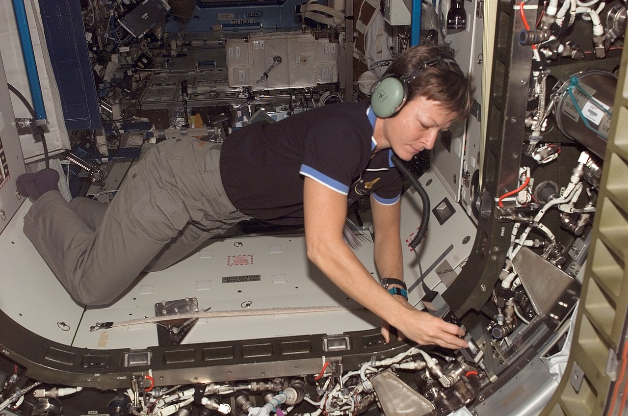


.jpg/1280px-ISS-47_BEAM_installation_(1).jpg)


.jpg)