The graphic symbols used for electrical components in circuit diagrams are covered by national and international standards, in particular:
IEC 60617 (also known as BS 3939).
There is also IEC 61131-3 – for ladder-logic symbols.
JIC JIC (Joint Industrial Council) symbols as approved and adopted by the NMTBA (National Machine Tool Builders Association). They have been extracted from the Appendix of the NMTBA Specification EGPl-1967.
ANSI Y32.2-1975 (also known as IEEE Std 315-1975[1] or CSA Z99-1975).
IEEE Std 91/91a: graphic symbols for logic functions (used in digital electronics). It is referenced in ANSI Y32.2/IEEE Std 315.
Australian Standard AS 1102 (based on a slightly modified version of IEC 60617; withdrawn without replacement with a recommendation to use IEC 60617).
The standards do not all agree, and use of unusual (even if standardized) symbols can lead to confusion and errors.[2]Symbols usage is sometimes idiosyncratic to engineering disciplines, and national or local variations to international standards exist. For example, lighting and power symbols used as part of architectural drawings may be different from symbols for devices used in electronics.
Common electronic symbols
Symbols shown are typical examples, not a complete list.[3][4]
Traces
Wire crossover symbols for circuit diagrams. The CAD symbol for insulated crossing wires is the same as the older, non-CAD symbol for non-insulated crossing wires. To avoid confusion, the wire "jump" (semi-circle) symbol for insulated wires in non-CAD schematics is recommended (as opposed to using the CAD-style symbol for no connection), so as to avoid confusion with the original, older style symbol, which means the exact opposite. The newer, recommended style for 4-way wire connections in both CAD and non-CAD schematics is to stagger the joining wires into T-junctions. The large dot signifies an electrical connection.
Grounds
The shorthand for ground is GND. Optionally, the triangle in the middle symbol may be filled in.
For multiple pole switches, a dotted or dashed line can be included to indicate two or more switch at the same time (see DPST and DPDT examples below).
Pushbutton, normally open, push-to-make (horizontal line on top)
UEXT connector based on a 5x2 shrouded header with notch key
ICs
Logic gates
For the symbols below: A and B are inputs, Q is output. Note: These letters are not part of the symbols.
There are variations of these logic gate symbols. Depending on the IC, the two-input gates below may have: 1) two or more inputs; 2) infrequently some have a second inverted Q output too.
Buffer gate with tri-state output control. (B is the tri-state control)
Flip-flops
For the symbols below: Q is output, Q is inverted output, E is enable input, internal triangle shape is clock input, S is Set, R is Reset (some datasheets use clear (CLR) instead of reset along the bottom).
There are variations of these flip-flop symbols. Depending on the IC, a flip-flop may have: 1) one or both outputs (Q only, Q only, both Q & Q); 2) one or both forced inputs along top & bottom (R only, S only, both R & S); 3) some inputs may be inverted.
Simple SR flip-flop (inverted S & R inputs)
Gated SR flip-flop
Gated D flip-flop (Transparent Latch)
Clocked D flip-flop (Set & Reset inputs)
Clocked JK flip-flop
Clocked T flip-flop
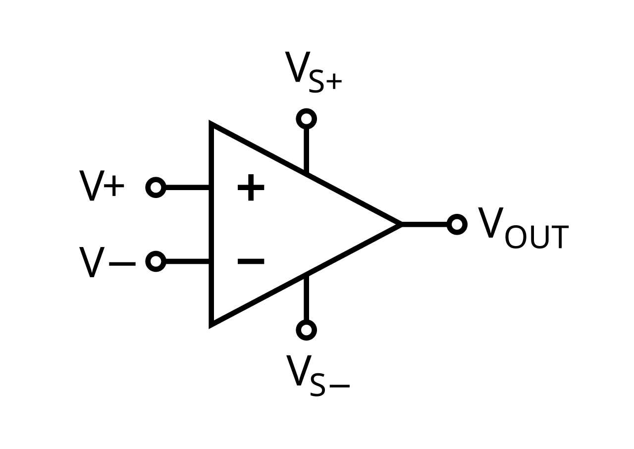
OpAmps
Note: The outside text isn't part of these symbols.
The shape of some electronic symbols have changed over time. The following historical electronic symbols can be found in old electronic books / magazines / schematics, and now considered obsolete.
Capacitors (historical)
All of the following are obsolete capacitor symbols.
^"IEEE Standard American National Standard Canadian Standard Graphic Symbols for Electrical and Electronics Diagrams (Including Reference Designation Letters)," in IEEE Std 315-1975 (Reaffirmed 1993), vol., no., pp.i-244, 1993, doi:10.1109/IEEESTD.1993.93397.
^ a bSobering, Tim (April 2008). Guidelines for Drawing Schematics.
^Circuit Symbols for all Electronic Components. Talking Electronics, 2013. Retrieved 01 Apr 2015.
^"Standards for Resistor Symbols". EePower. EETech Media. Retrieved September 13, 2021.
^"A4.11 Envelope or Enclosure". ANSI Y32.2-1975 (PDF). Archived from the original (PDF) on 2022-10-09. Retrieved 2020-12-29. The envelope or enclosure symbol may be omitted from a symbol referencing this paragraph, where confusion would not result
Further reading
Standards
IEC 60617 : Graphical Symbols for Diagrams; 2012.
IEEE 315 : Graphic Symbols for Electrical and Electronics Diagrams (including Reference Designation Letters); 1975.
U.S. DoD MIL-STD-806B : Graphical Symbols for Logic Diagrams; 1962. (RevB in 1962)
Books
Beginner's Guide to Reading Schematics; 4th Ed; Stan Gibilisco; McGraw-Hill, 224 pages; 2018; ISBN 978-1260031119.
How to Read Schematic Diagrams; 5th Ed; Donald Herrington; Literary Licensing; 130 pages; 2011; ISBN 978-0672224577. (4ed in 1986)(2ed in 1967)
How to Read Electronic Circuit Diagrams; 2nd Ed; Robert Brown, Paul Lawrence, James Whitson; Tab Books; 214 pages; 1988; ISBN 978-0830628803. (2ed in 1988)
Engineer's Mini-Notebook : Schematic Symbols, Device Packages, Design and Testing; 1st Ed; Forrest M. Mims III; Radio Shack; 48 pages; 1988. (1ed in 1988)
External links
Wikimedia Commons has media related to Electrical symbols.


.svg/1280px-IEEE_315_Transmission_Path_Symbols_(75).svg.png)
.svg/1280px-IEEE_315_Transmission_Path_Symbols_(80).svg.png)
.svg/1280px-IEEE_315_Transmission_Path_Symbols_(78).svg.png)
.svg/1280px-IEEE_315_Fundamental_Items_Symbols_(90).svg.png)
.svg/1280px-IEEE_315_Fundamental_Items_Symbols_(92).svg.png)
_8.7.3.svg/1280px-IEEE_315-1975_(1993)_8.7.3.svg.png)


,_and_Potentiometer_symbols.svg/1280px-Resistor,_Rheostat_(variable_resistor),_and_Potentiometer_symbols.svg.png)
_2.1.13.svg/1280px-IEEE_315-1975_(1993)_2.1.13.svg.png)
![Thermistor (ANSI).[5] Use -t for NTC symbol. Use +t for PTC symbol.](http://upload.wikimedia.org/wikipedia/commons/thumb/e/e8/IEEE_315-1975_(1993)_2.1.12.1.2.svg/1280px-IEEE_315-1975_(1993)_2.1.12.1.2.svg.png)
_2.1.6.a.svg/1280px-IEEE_315-1975_(1993)_2.1.6.a.svg.png)
![General capacitor (IEC‑style); sometimes drawn with one plate curved[2]](http://upload.wikimedia.org/wikipedia/commons/thumb/7/73/IEEE_315_Fundamental_Items_Symbols_(32).svg/1280px-IEEE_315_Fundamental_Items_Symbols_(32).svg.png)
.svg/1280px-IEEE_315_Fundamental_Items_Symbols_(38).svg.png)
.svg/1280px-IEEE_315_Fundamental_Items_Symbols_(41).svg.png)

.svg/1280px-IEEE_315_Fundamental_Items_Symbols_(36).svg.png)


.png/1280px-Bridge_Rectifier_for_single-phase_alternating_current_(symbolic_diagram).png)


_8.6.2.svg/1280px-IEEE_315-1975_(1993)_8.6.2.svg.png)
_8.6.1.svg/1280px-IEEE_315-1975_(1993)_8.6.1.svg.png)
_8.6.17.svg/1280px-IEEE_315-1975_(1993)_8.6.17.svg.png)


.svg/1280px-IEEE_315_Contacts,_Switches,_Contactors,_and_Relays_Symbols_(57).svg.png)
.svg/1280px-IEEE_315_Contacts,_Switches,_Contactors,_and_Relays_Symbols_(58).svg.png)
.svg/1280px-IEEE_315_Contacts,_Switches,_Contactors,_and_Relays_Symbols_(59).svg.png)


.svg/1280px-IEEE_315_Contacts,_Switches,_Contactors,_and_Relays_Symbols_(85).svg.png)
.svg/1280px-IEEE_315_Contacts,_Switches,_Contactors,_and_Relays_Symbols_(87).svg.png)
.svg/1280px-IEEE_315_Contacts,_Switches,_Contactors,_and_Relays_Symbols_(89).svg.png)
.svg/1280px-IEEE_315_Contacts,_Switches,_Contactors,_and_Relays_Symbols_(84).svg.png)
.svg/1280px-IEEE_315_Contacts,_Switches,_Contactors,_and_Relays_Symbols_(86).svg.png)
.svg/1280px-IEEE_315_Contacts,_Switches,_Contactors,_and_Relays_Symbols_(88).svg.png)


.svg/1280px-IEEE_315_Fundamental_Items_Symbols_(55).svg.png)
.svg/1280px-IEEE_315_Fundamental_Items_Symbols_(58).svg.png)
.svg/1280px-IEEE_315_Fundamental_Items_Symbols_(61).svg.png)
.svg/1280px-IEEE_315_Fundamental_Items_Symbols_(60).svg.png)
.svg/1280px-IEEE_315_Transmission_Path_Symbols_(26).svg.png)
.svg/1280px-IEEE_315_Transmission_Path_Symbols_(30).svg.png)
.svg/1280px-IEEE_315_Transmission_Path_Symbols_(29).svg.png)
.svg/1280px-IEEE_315_Transmission_Path_Symbols_(31).svg.png)
.svg/1280px-IEEE_315_Transmission_Path_Symbols_(27).svg.png)


_Symbol.svg/1280px-JK_Flip-flop_(Simple)_Symbol.svg.png)


.svg/1280px-IEEE_315_Fundamental_Items_Symbols_(113).svg.png)


_8.6.10.1.b.svg/1280px-IEEE_315-1975_(1993)_8.6.10.1.b.svg.png)
_8.6.11.1.b.svg/1280px-IEEE_315-1975_(1993)_8.6.11.1.b.svg.png)


